Eureka AIR delivers breakthrough ideas for toughest innovation challenges, trusted by R&D personnel around the world.

Rotary cutting tool with stable structure

A technology of rotating cutting tools and stable structure, applied in the field of metal cutting tools, can solve the problems of reducing the precision and cutting efficiency of the machined surface, reducing the cutting speed and precision of the cutting tool, unstable structure of the cutting tool groove, etc., so as to improve the machined surface. Accuracy and cutting efficiency, the effect of increasing cutting speed and precision, reducing contact strength requirements

Active Publication Date: 2014-07-02
ZHUZHOU CEMENTED CARBIDE CUTTING TOOLS CO LTD
View PDF7 Cites 0 Cited by
  • Summary
  • Abstract
  • Description
  • Claims
  • Application Information

AI Technical Summary

Problems solved by technology

Due to the gap between the connecting piece and the counterbore of the above-mentioned cutting tool, the centrifugal force of the tool holder is mainly provided by the clamping force between the connecting piece and the tool holder and the friction force between the tool groove and the tool holder. When cutting, When the clamping force between the connecting piece and the tool holder and the friction between the tool groove and the tool holder are insufficient to balance the centrifugal force, the tool holder is prone to loosening or even centrifugally flying out of the tool groove, and the structure of the cutting tool groove is unstable. , The positioning accuracy is low; at the same time, when the cutting blade bears a large cutting force in the radial direction, the connecting piece slides in the countersunk hole, and the tool holder rotates around the countersunk hole axis in the tool groove, thus greatly reducing the cutting time. The cutting speed and precision of the tool are prone to vibration during machining, which reduces the machining surface accuracy and cutting efficiency

Method used


Image

  • Rotary cutting tool with stable structure
  • Rotary cutting tool with stable structure
  • Rotary cutting tool with stable structure

Examples


Embodiment Construction

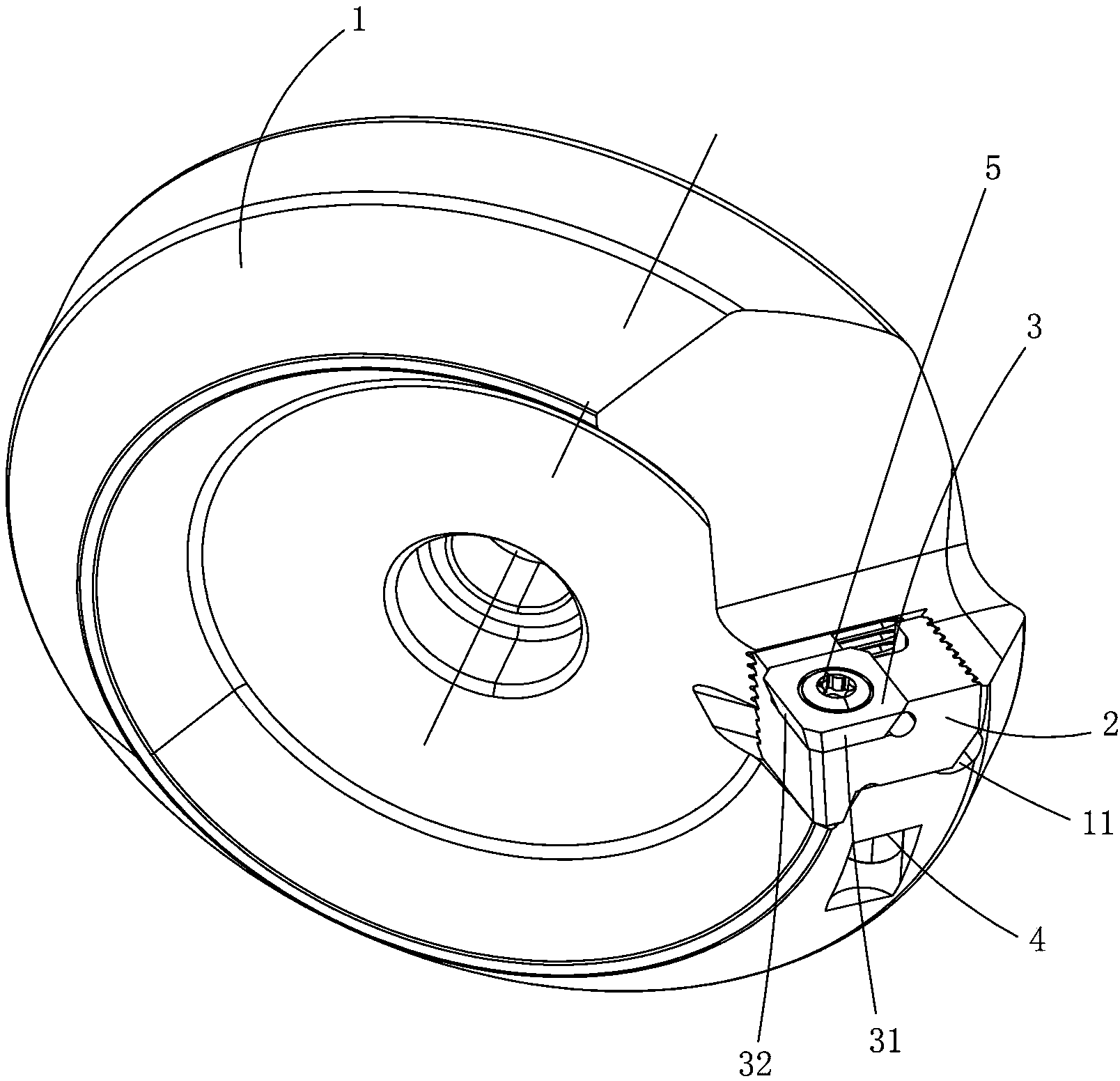
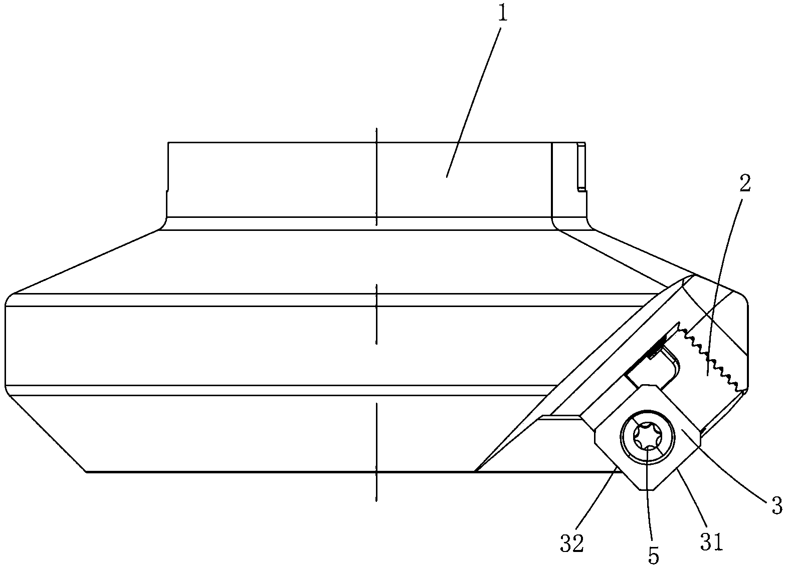
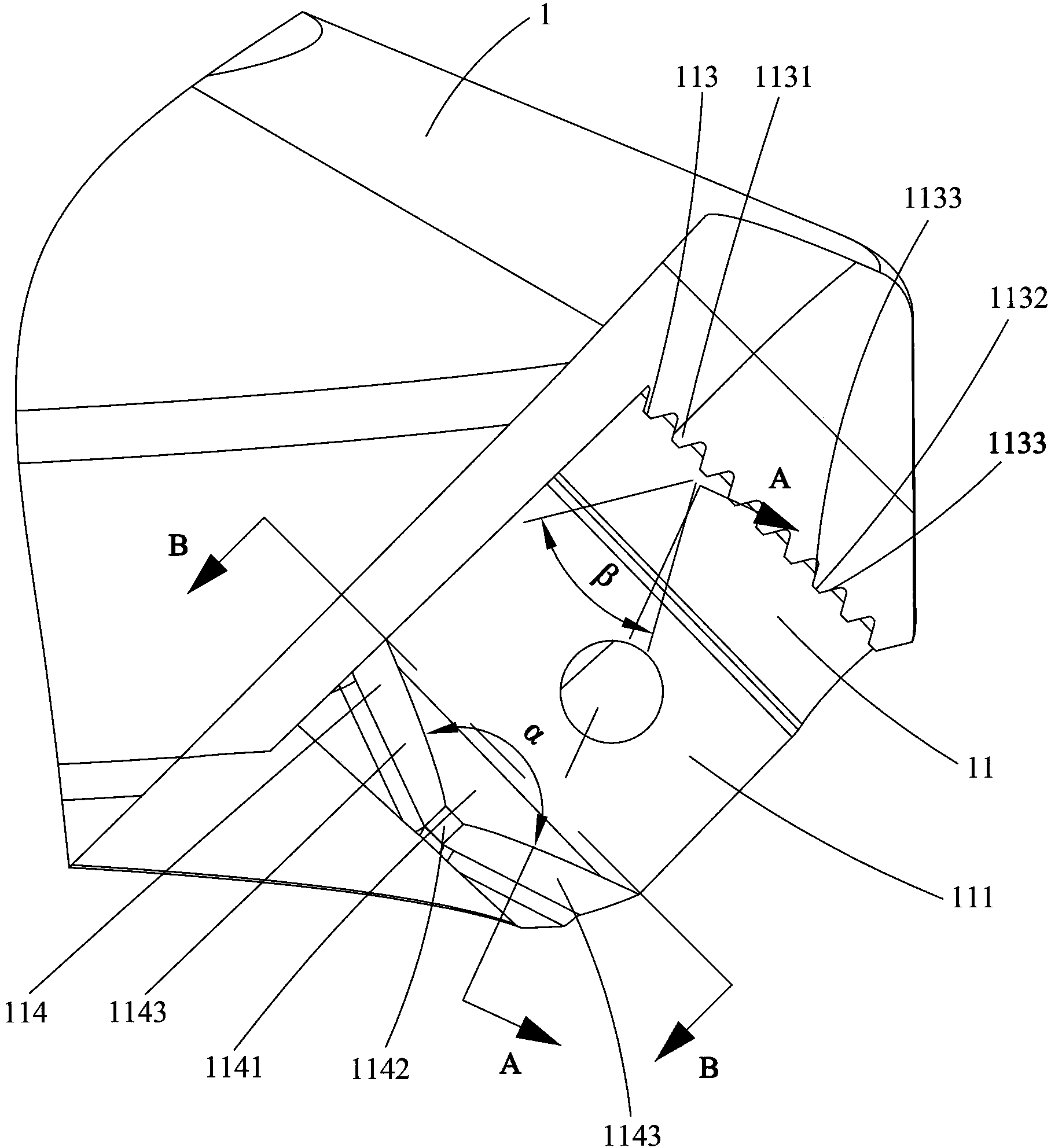
[0032] Figure 1 to Figure 9 A structurally stable rotary cutting tool embodiment of the present invention is shown, the rotary cutting tool includes a rotary cutter body 1, a tool holder 2, a cutting blade 3, a tool holder fastener 4 and a blade fastener 5, the rotary cutter body 1 is provided with a sipe 11 surrounded by a bottom positioning surface 111, a side positioning surface 112 and an end positioning surface 113. The cutting blade 3 is fixed on the tool holder 2 through a blade fastener 5. The side cutting edge 31 is opposite, the end positioning surface 113 is opposite to the end cutting edge 32 of the cutting blade 3, and the end of the sipe 11 near the end cutting edge 32 is provided with a front end positioning surface 114 intersecting with the bottom positioning surface 111, and the front end positioning surface 114 is provided with a first protrusion 1141, and the bottom of the tool holder 2 is provided with a first recess 21 at the end near the end cutting edge...


PUM


Abstract

The invention discloses a rotary cutting tool with stable structure, comprising a rotary tool body, a tool holder, a cutting blade, a tool holder fastener, and a blade fastener. The rotary tool body is provided with a tool groove enclosed by a bottom positioning face, side positioning faces and end positioning faces. The cutting blade is fixed to the tool holder through the blade fastener. The side positioning faces face a side cutting edge of the cutting blade. The end positioning faces face an end cutting edge of the cutting blade. One end, close to the end cutting edge, of the tool groove is provided with a front end positioning face intersecting with the bottom positioning face; the front end positioning face is provided with a first protrusion. One end, close to the end cutting edge, of the bottom of the tool holder is provided with a first recess in contact fit with the first protrusion. The rotary cutting tool with the stable structure has the advantages that connection is stable, positioning precision is high, flipping control ability is high, vibration is low, and machining precision is high.

Description

technical field [0001] The invention relates to a metal cutting tool, in particular to a structurally stable rotary cutting tool. Background technique [0002] The Chinese patent document whose publication number is CN101992305 discloses a cutting tool, including a cutter body, a tool holder, a cutting blade, a connector and a fastener. Placed in the tool slot, the tool holder clamps the cutting blade on the tool holder through fasteners. The tool body is provided with a countersunk hole that communicates with the tool slot. The connecting piece is installed in the countersunk hole and threaded with the tool holder. Connection, the tool groove presses and fixes the tool holder through the connecting piece, and the cutting blade and the tool holder, and the tool holder and the tool body are mainly positioned on a plane. Due to the gap between the connecting piece and the counterbore of the above-mentioned cutting tool, the centrifugal force of the tool holder is mainly provi...

Claims


Application Information

Patent Timeline
Patent Type & Authority Applications(China)
IPC IPC(8): B23B27/00
CPCB23B27/00
Inventor 江爱胜刘敏
Owner ZHUZHOU CEMENTED CARBIDE CUTTING TOOLS CO LTD
Why Eureka
Eureka Blog
Learn More