Pressing-down tire mounting mechanism and tire forming mounting method thereof
A press-fitting and tire technology, applied in tires, other household appliances, household appliances, etc., can solve the problems of high technical requirements, high personal labor intensity and high labor intensity of workers, so as to reduce workers' labor intensity, improve labor efficiency, The effect of high safety
- Summary
- Abstract
- Description
- Claims
- Application Information
AI Technical Summary
Problems solved by technology
Method used
Image

Examples
Embodiment Construction
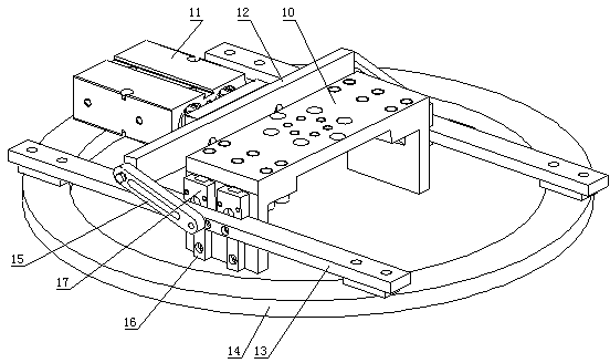
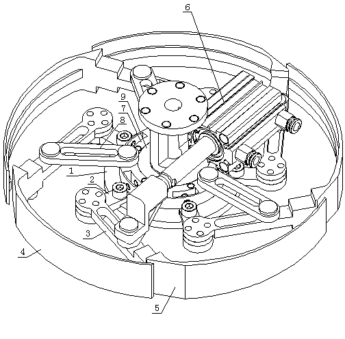
[0020] The present invention will be further described in detail below in conjunction with a tire vulcanizing machine stereotyping and tire mounting manipulator and a tire shaping tire mounting method that have adopted the tire under-pressing tire mounting mechanism of the present invention.
[0021] In this specific embodiment, firstly, a tire vulcanizing machine stereotyping and loading manipulator is disclosed, which includes a vertically arranged connecting shaft with a telescopic function, which also includes a bottom press-fitting tire horizontally arranged on the connecting shaft from top to bottom. mechanism and an inner support shaping mechanism, the inner support shaping mechanism is used to prop up the raw tire from the inside and complete the shaping, and the lower pressure tire installation mechanism is used to press the raw tire on the inner support shaping mechanism into the mold to complete Install tires. Among them, the structure of the internal support shapin...
PUM
 Abstract
Description
Claims
Application Information
PatSnap Eureka turns technology decisions into work you can execute. Powered by our Innovation Knowledge Graph, it runs expert workflows across engineering, life sciences, materials and intellectual property. Get your review-ready output in minutes.


