Method for controlling vacuum degree of automobile brake boosting system

A power assist system and automobile braking technology, applied in the direction of brakes, brake transmissions, vehicle components, etc., can solve problems such as noise interference, high EVP cost, and reduced fuel economy

Active Publication Date: 2014-07-02
SAIC MOTOR
View PDF4 Cites 15 Cited by
  • Summary
  • Abstract
  • Description
  • Claims
  • Application Information

AI Technical Summary

Problems solved by technology

[0003] The automobile brake system adopts vacuum booster braking. The conventional brake booster system uses the vacuum degree of the engine intake system as the driving energy. Since the vacuum degree of the engine is affected by many factors, especially the small emission of energy saving and emission reduction in recent years The trend, the substantial increase in emission control requirements, and the increasing requirements for vehicle braking system capabilities have led to a phenomenon that a large number of vehicle models cannot meet the design requirements of the braking system only by relying on the vacuum boost of the engine intake.
The commonly used solution in the industry is to add electronic vacuum pump system EVP or mechanical vacuum pump system MVP to the vehicle. EVP is expensive and is generally used for after-sales installation in special areas, and it will cause noise interference. MVP must be designed and set aside during engine design. Install the interface, because the engine is directly driven full-time, so MVP will increase engine resistance and reduce fuel economy

Method used


Image

  • Method for controlling vacuum degree of automobile brake boosting system
  • Method for controlling vacuum degree of automobile brake boosting system
  • Method for controlling vacuum degree of automobile brake boosting system

Examples


Embodiment 1

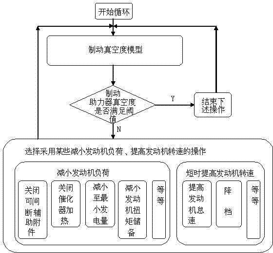
[0028] A method for controlling the vacuum degree of a brake booster system of an automobile, comprising the following steps, first setting a vacuum degree threshold and a delay time according to vehicle design parameters, then establishing a brake vacuum degree model, and using the brake vacuum degree every time a delay time passes The current vacuum degree of the brake booster is judged once based on the vacuum degree model and the vacuum degree threshold value, and the following selection is made according to the judgment result: 1) When the current vacuum degree of the brake booster meets the vacuum degree threshold value, wait for the next comparison; 2. ) When the current vacuum of the brake booster does not meet the vacuum threshold requirement, increase the vacuum of the brake booster by reducing the engine load and / or increasing the engine speed.

[0029] Vacuum degree in this patent = ambient air pressure - measuring point air pressure

[0030] The brake vacuum degre...


PUM


Abstract

The invention relates to the field of automobile brake systems, in particular to a method for controlling the vacuum degree of an automobile brake boosting system. The method for controlling the vacuum degree of the automobile brake boosting system comprises the steps that a vacuum degree threshold value and delay time sections are firstly set according to automobile style design parameters, a brake vacuum degree model is established, the current vacuum degree of a brake booster is judged once after each delay time section, and when the current vacuum degree of the brake booster satisfies the requirement for the vacuum degree threshold value, a next comparison is to be conducted; when the current vacuum degree of the brake booster does not meet the requirement for the vacuum degree threshold value, the vacuum degree of the brake booster is increased through reduction of engine loads and /or increase of the rotation speed of an engine. According to the method, the requirement for the vacuum degree of a brake system is preferentially met through reduction of the engine loads and/or increase of the rotation speed of the engine, it is guaranteed that the market expected brake capacity is achieved, meanwhile, an electronic vacuum pump system or a mechanical vacuum pump system is omitted, the functions of cost reduction and efficiency improvement are achieved, and compared with other products, the market competitiveness is improved.

Description

technical field [0001] The invention relates to the fields of automobile engine control systems and brake systems, in particular to a method for controlling the vacuum degree of a brake booster system. Background technique [0002] The development of contemporary automobile technology can be described as rapid progress, especially China's automobile industry has developed into the world's largest consumer country. However, with the increasingly stringent low-cost requirements for automobile design and intensified competition, as well as the increasing technical requirements of users for automobiles, the importance of electronic control systems for automobile products has become increasingly prominent. [0003] The automobile brake system adopts vacuum booster braking. The conventional brake booster system uses the vacuum degree of the engine intake system as the driving energy. Since the vacuum degree of the engine is affected by many factors, especially the small emission o...

Claims


Application Information

Patent Timeline
Patent Type & Authority Applications(China)
IPC IPC(8): B60T13/72
Inventor 吴铭淞康永胡锫
Owner SAIC MOTOR
Why Eureka
Try Eureka