Hydraulic lock with pilot one-way valve

A one-way valve and hydraulic lock technology, applied in the field of hydraulic locks, can solve the problems of increasing the volume of the valve, shorten the service life of the hydraulic lock, etc., and achieve the effect of reducing power loss and no heat

Active Publication Date: 2014-07-02
四川德恩精工科技股份有限公司
View PDF8 Cites 8 Cited by
  • Summary
  • Abstract
  • Description
  • Claims
  • Application Information

AI Technical Summary

Problems solved by technology

use figure 1 The design of the valve will increase the volume of the valve and make it difficult to manufacture. At the same time, due to the e

Method used


Image

  • Hydraulic lock with pilot one-way valve
  • Hydraulic lock with pilot one-way valve
  • Hydraulic lock with pilot one-way valve

Examples


Example Embodiment

[0013] The present invention will be further described below in conjunction with the accompanying drawings. The protection scope of the present invention is not limited to the following:

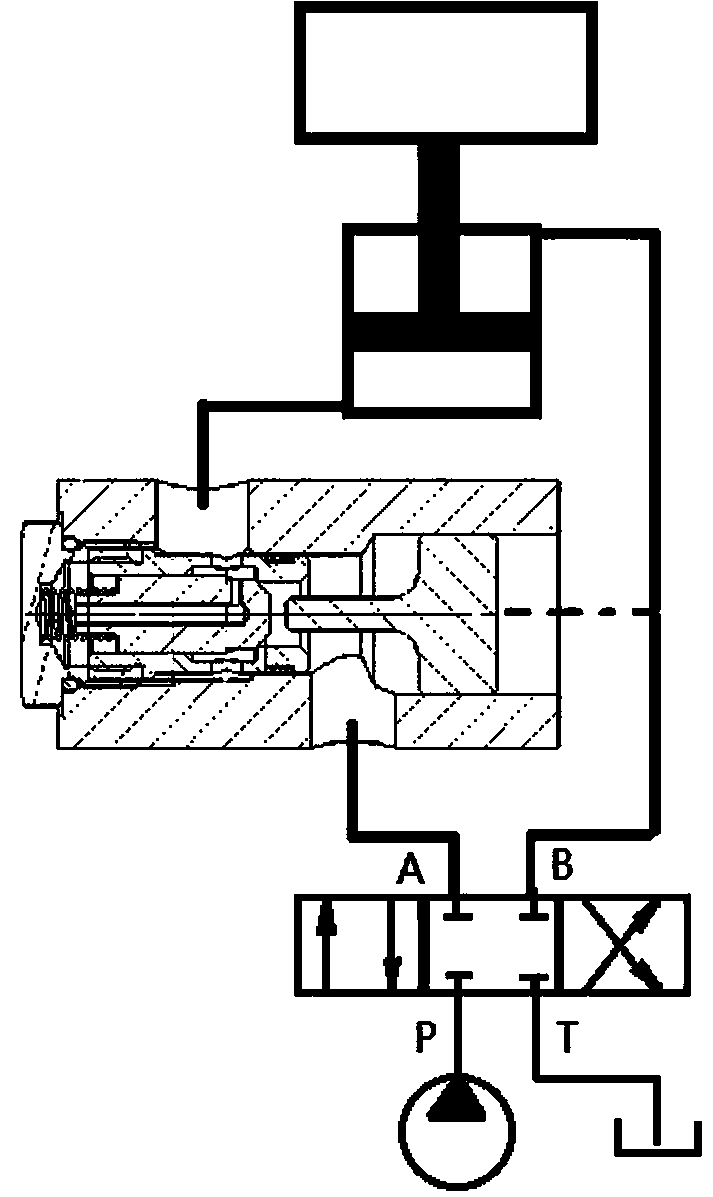
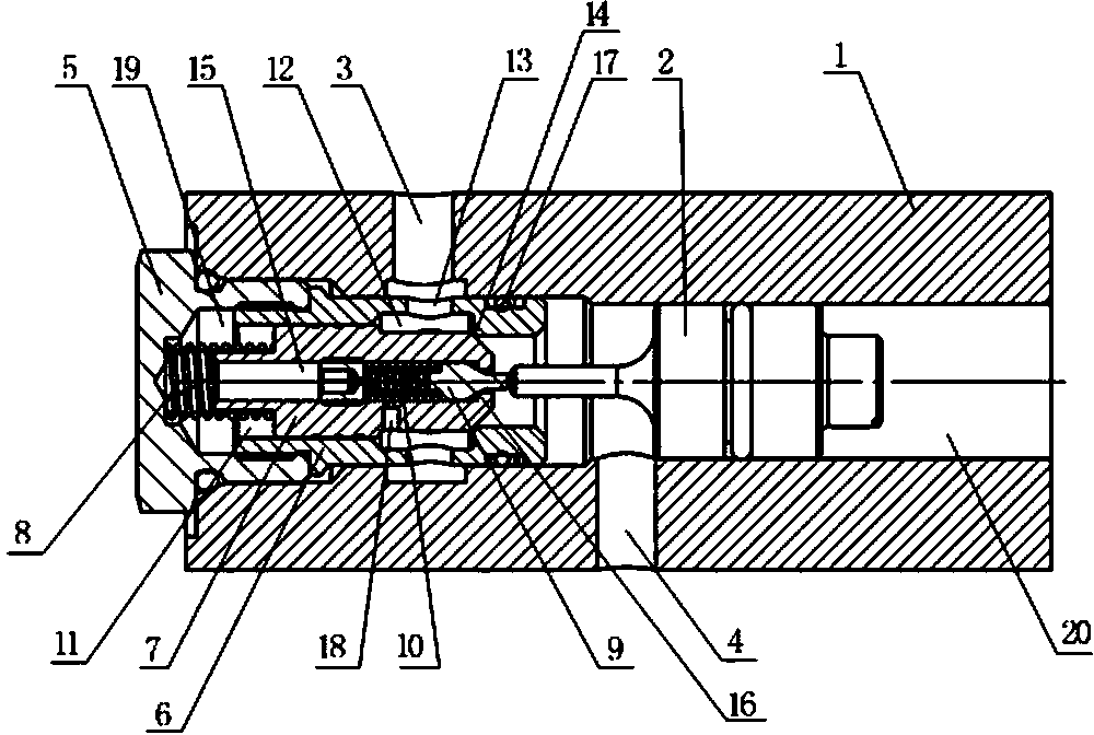
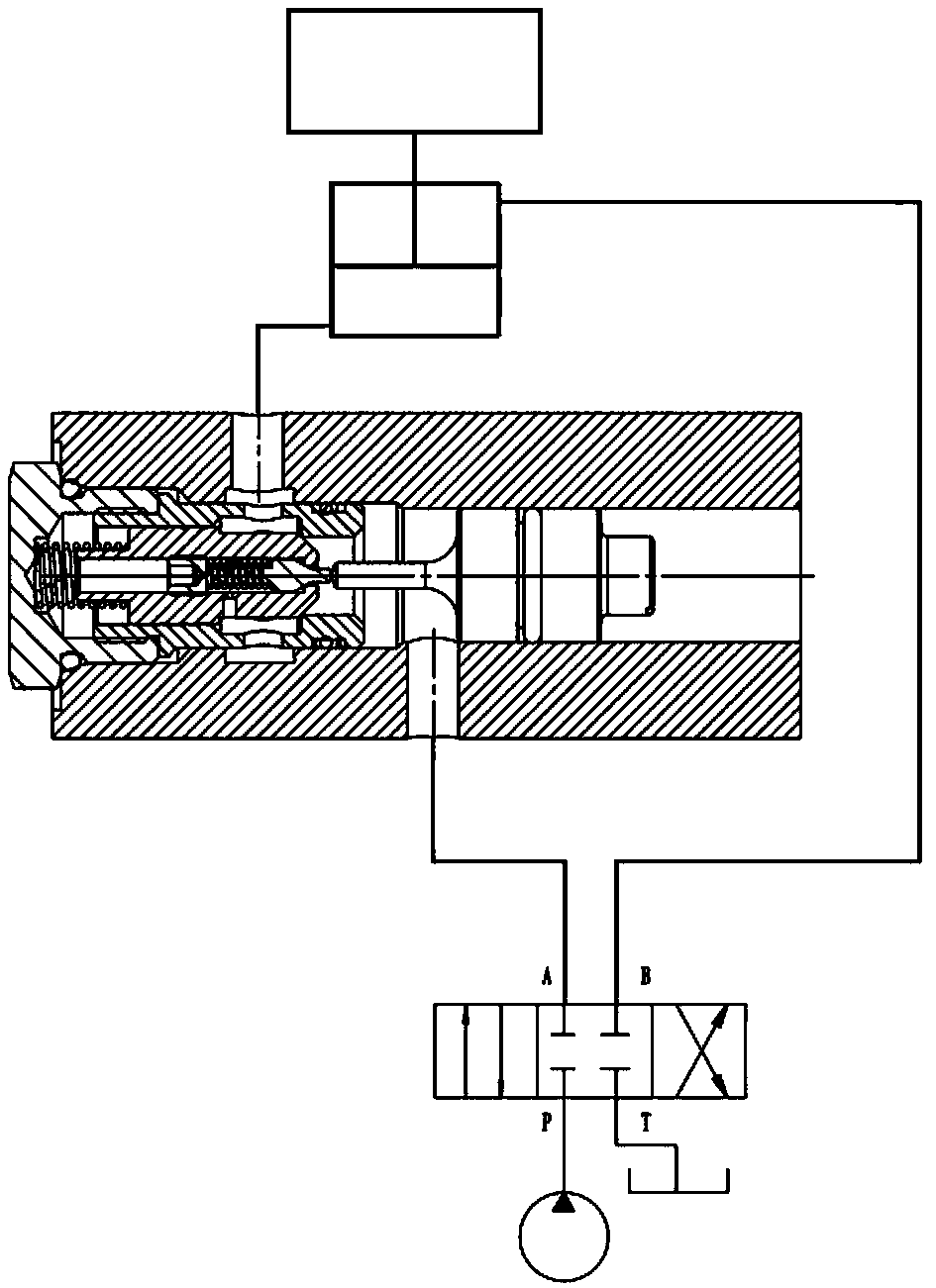
[0014] Such as figure 2 As shown, a hydraulic lock with pilot check valve includes a valve body 1, a piston 2 and a cartridge type check valve with pilot. The top of one end of the valve body 1 is provided with an oil port I3, and the other end of the valve body 1 There is an oil port II4 at the bottom of the valve body, and a through hole is provided in the valve body 1. The oil port I3 and the oil port II4 are both connected with the through hole. The through hole is divided into the chamber I19 and the chamber II20 by the oil port II4. The one-way valve with pilot includes the valve cover 5, the valve sleeve 6, the main valve core 7, the main valve core spring 8, the pilot valve core 9 and the pilot valve spring 10. The valve sleeve 6 is arranged in the chamber I19 and the valve sleeve 6 A ...


PUM


Abstract

The invention discloses a hydraulic lock with pilot one-way valve comprising a valve (1), a piston (2) and an inserting polit one-way valve. The top of one end of the valve (1) is provided with an oil port I (3), the bottom of the other end of the valve (1) is provided with an oil port II (4), and the valve (1) is provided with through holes; the inserting polit one-way valve comprises a valve cover (5), a valve sleeve (6), a main valve core (7), a main valve core spring (8), a pilot valve core (9) and a pilot valve spring (10); a through hole I (11) is provided with an annular groove (12) inside, the bottom of the pilot valve core (9) is provided with a conical structure as same as a pilot valve seat (16), the main valve core (7) is provided with a throttle small hole (18) communicating a through hole II (15) and the annular groove (12). The hydraulic lock has the advantages that structure is simple, size is small, service life is long, weight performs steady descending motions, system power consumption is small, and the system heats rarely.

Description

technical field [0001] The invention relates to a hydraulic lock for lifting and lowering heavy objects with hydraulic oil, in particular to a hydraulic lock with a pilot check valve. Background technique [0002] In the application of construction machinery, agricultural machinery and construction machinery, it is often necessary to lift and lower heavy objects, such as the lifting mechanism of the crane, the luffing of the boom, the boom of the loader, the lifting mechanism of the tractor, etc. It is necessary to lock the weight or oil cylinder or piston in a certain position, and at the same time, to achieve a smooth descent during the descent. The usual solution is to use a balance valve. However, the structure of the balance valve is relatively complicated, and the manufacturing cost is high, and it is often used in a hydraulic system with a large flow. [0003] Therefore, people usually use hydraulic locks instead of balance, the hydraulic lock works as figure 1 As s...

Claims


Application Information

Patent Timeline
IPC IPC(8): F15B15/26F16K15/02F16K31/124
Inventor 雷永志艾奇
Owner 四川德恩精工科技股份有限公司
Why Eureka
Try Eureka