Collimating light source module and display device

A technology of collimating light source and display device, which is applied in display device, electric light source, lighting device, etc., can solve the problems of inability to provide high collimation, poor viewing angle control ability of display device, and reduced image contrast, etc., so as to improve the light source. The effect of using efficiency

Inactive Publication Date: 2014-07-02
CORETRONIC
View PDF15 Cites 2 Cited by
  • Summary
  • Abstract
  • Description
  • Claims
  • Application Information

AI Technical Summary

Problems solved by technology

[0003] Therefore, the current light source module of the head-up display device uses the technology of light pipe or integrating column and light-emitting diode array to provide a uniform light source. The viewing angle control ability of the display device is poor, and the divergence angle of the illumination beam after it exits the display panel is too large.
When the display

Method used


Image

  • Collimating light source module and display device
  • Collimating light source module and display device
  • Collimating light source module and display device

Examples


Embodiment Construction

[0071] The aforementioned and other technical contents, features and effects of the present invention will be clearly presented in the following detailed descriptions of multiple embodiments with reference to the drawings. The directional terms mentioned in the following embodiments, such as up, down, front, back, left, right, etc., are only directions referring to the attached drawings. Accordingly, the directional terms are used to illustrate, not to limit, the invention.

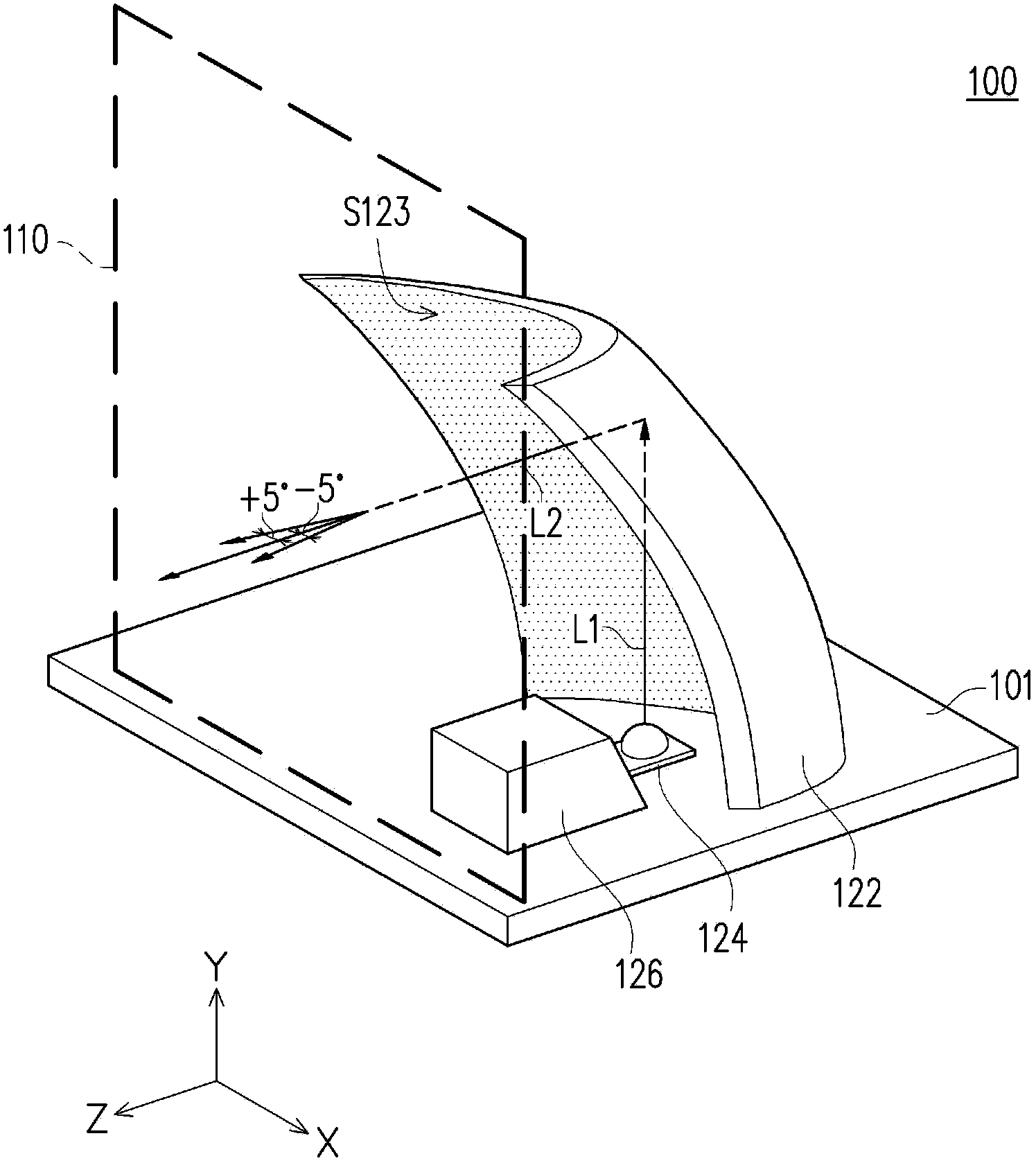
[0072] figure 1 A three-dimensional schematic diagram of a light source module according to an embodiment of the present invention is shown. Please refer to figure 1 The light source module 100 of this embodiment includes a bottom plate 101 , a reflective element 122 , a light emitting element 124 and a light shielding element 126 , wherein a virtual light-emitting plane 110 is perpendicular to the bottom plate 101 . The reflective element 122 is disposed on the base plate 101 . The reflective element...


PUM


Abstract

A collimating light source module comprises a base plate, at least one reflecting element, at least one light-emitting element and at least one light-shielding element, wherein the reflecting element comprises a reflecting curved face and is arranged on the base plate, the light-emitting element is arranged on the base plate and used for providing lighting beams for the reflecting curved face, the light shielding element is arranged on the base plate, the light-emitting element is located between the light shielding element and the reflecting element, the reflecting curved face is used for reflecting the lighting beams and converting the lighting beams into parallel collimating beams, and the parallel collimating beams are parallel to the base plate.

Description

technical field [0001] The invention relates to a light source device, and in particular to an image display device. Background technique [0002] US Patent No. 7,932,960 discloses a head-up display device, in which an illumination beam is emitted from a light-emitting element, and then transmitted to a display panel through a light pipe or an integrating column. This kind of display device has high uniformity of the illuminating beam incident into the integrating column, but after the illuminating beam exits the effective area of ​​the integrating column, the energy is reduced, which easily produces dark areas. In order to solve this problem, the light-emitting device of this patent needs to use a light-emitting diode array to provide a uniform light source in a certain area. Moreover, as the area increases, the number of light-emitting diodes in the light-emitting diode array also increases. The head-up display device disclosed in US Pat. No. 7,513,668 also uses an LED a...

Claims


Application Information

Patent Timeline
IPC IPC(8): F21S2/00F21V7/06F21V7/08G09F19/12
Inventor 庄福明游志杰蔡汉文
Owner CORETRONIC
Why Eureka
Try Eureka