Blowing-type burner control method

A control method and burner technology, applied in the direction of controlling combustion, lighting and heating equipment, etc., can solve the problems of flame temperature drop, increase in size and power, increase in air supply, etc., to prevent ignition and deflagration, and improve heat exchange efficiency , the effect of improving safety

Active Publication Date: 2014-07-02
SHANGHAI HESEN ELECTRO MACHINERY
View PDF8 Cites 19 Cited by
  • Summary
  • Abstract
  • Description
  • Claims
  • Application Information

AI Technical Summary

Problems solved by technology

[0002] Nowadays, the usual blast burner adopts the diffusion blast combustion method. This kind of mechanism is simple and easy to manufacture, but it has low combustion intensity, and the combustion requires a large volume of the mechanism and consumes a lot of materials. In order to make the combustion complete, it must be supplied Too much excess air - the size and power of the fan must be increased, low combustion temperature - low thermal efficiency and other defects, the main reason is that the flame burns with the help of the surrounding air after ignition, and the formed flame has a kind of isolation from the air The function makes it difficult for the air to enter the center of the flame and fully contact with the gas to achieve complete combustion
[0003] The current method is to greatly increase the air supply. Through the supply of a large amount of air, the contac

Method used


Image

  • Blowing-type burner control method

Examples


Embodiment 1

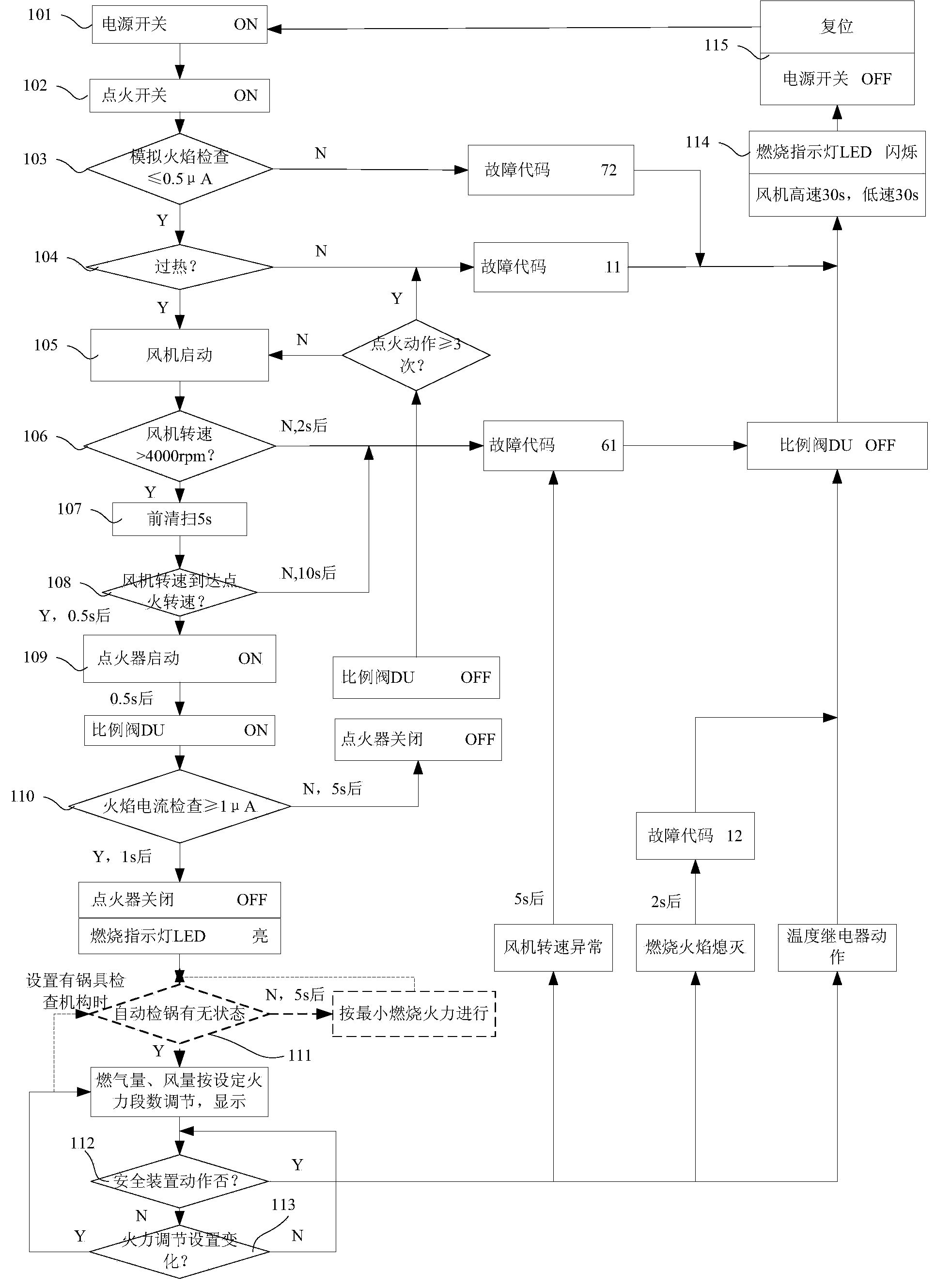
[0030] A method for controlling a blast burner. The blast burner controlled by the method includes a combustion box, a blower, an electric controller and an operator. The combustion box is provided with a flame current sensing needle, a gas proportional valve assembly, and an ignition The electric controller is connected to the blower, the operator, the flame current sensing needle, the gas proportional valve assembly, the igniter and the temperature relay, respectively. The gas proportional valve assembly includes an electric shut-off valve and an electric regulating port. The operator is mainly responsible for Issue various instructions for use and stop use, and display the use status and alarm code when a failure occurs.

[0031] Such as figure 1 As shown, the control method includes the following steps:

[0032] Step 101, the power switch is turned on, the power indicator on the operator is on, the firepower indicator LED is displayed according to the number of unpowered segme...

Embodiment 2

[0051] The difference between this embodiment and Embodiment 1 is that, in this embodiment, a=4000rpm in step 107, and the purge time is 0.5s.

Embodiment 3

[0053] The difference between this embodiment and Embodiment 1 is that in this embodiment, a=3000rpm in step 107, and the purge time is 12s.


PUM


Abstract

The invention relates to a blowing-type burner control method which comprises the following steps that an electric controller receives an ignition instruction and conducts slash fire detection, overheat detection and draught fan rotating speed detection sequentially; the electric controller controls an air blower to blow and sweep a combustion box at the rotating speed a; the electric controller controls the rotating speed of the air blower to be a set ignition rotating speed b, an igniter is started, a power shut-off valve on a gas proportion valve assembly is controlled to be opened, and an electric adjustment opening in the gas proportion valve assembly is opened to an ignition opening degree according to a set ignition current; after the successful ignition, the electric controller synchronously controls the opening degree of the electric adjustment opening and the rotating speed of the air blower according to the burning power input by a manipulator; when the electric controller receives a stop work instruction from the manipulator, the gas proportion valve assembly is closed and the air blower continues to run for set period of time. Compared with the prior art, the blowing-type burner control method has the advantages of being high in heat exchange efficiency, high in safety and the like.

Description

Technical field [0001] The invention relates to a combustion control method, in particular to a control method of a blast burner. Background technique [0002] Nowadays, the usual blast burner adopts the diffuse blast combustion method. This mechanism is simple and convenient to manufacture, but it has low combustion intensity. The combustion requires a large body and consumes a lot of materials. In order to achieve sufficient combustion, it must be supplied with more Excessive air-the size and power of the fan must be increased, the combustion temperature is low-the thermal efficiency is low, etc. The main reason is that the flame burns under the support of the surrounding air after ignition, and the formed flame has a kind of isolation from the air The effect makes it difficult for air to enter the center of the flame and fully contact the gas to achieve complete combustion. [0003] The current method is to greatly increase the air supply. Through the supply of a large amount o...

Claims


Application Information

Patent Timeline
IPC IPC(8): F23N5/00
Inventor 杜一鸣
Owner SHANGHAI HESEN ELECTRO MACHINERY
Why Eureka
Try Eureka