Air conditioner

A technology of air conditioner and heat exchanger, which is applied in air conditioning system, space heating and ventilation details, space heating and ventilation, etc. It can solve the problems of air blower blowing into the room, difficulty in condensing water, and reduction in the number of columns, etc. Achieve the effect of reliably leading into the water receiving tray and preventing the condensed water from splashing

Active Publication Date: 2014-07-02
PANASONIC CORP
View PDF10 Cites 7 Cited by
  • Summary
  • Abstract
  • Description
  • Claims
  • Application Information

AI Technical Summary

Problems solved by technology

However, in the existing air conditioner, there is no disclosure of any condensed water drainage structure, especially in the lower part of the front heat exchanger 1 due to the reduction in the number of rows, and it is formed independently from other parts, Therefore, the condensed water on the upper part of the front heat exchanger is not easy to be introduced into the water tray, and there is a problem that it is easy to be blown into the room by the blower

Method used


Image

  • Air conditioner
  • Air conditioner
  • Air conditioner

Examples


no. 1 Embodiment approach )

[0029] The air conditioner according to this embodiment includes an indoor unit 100 and an outdoor unit (not shown). The indoor unit 100 is generally installed, for example, on a wall indoors.

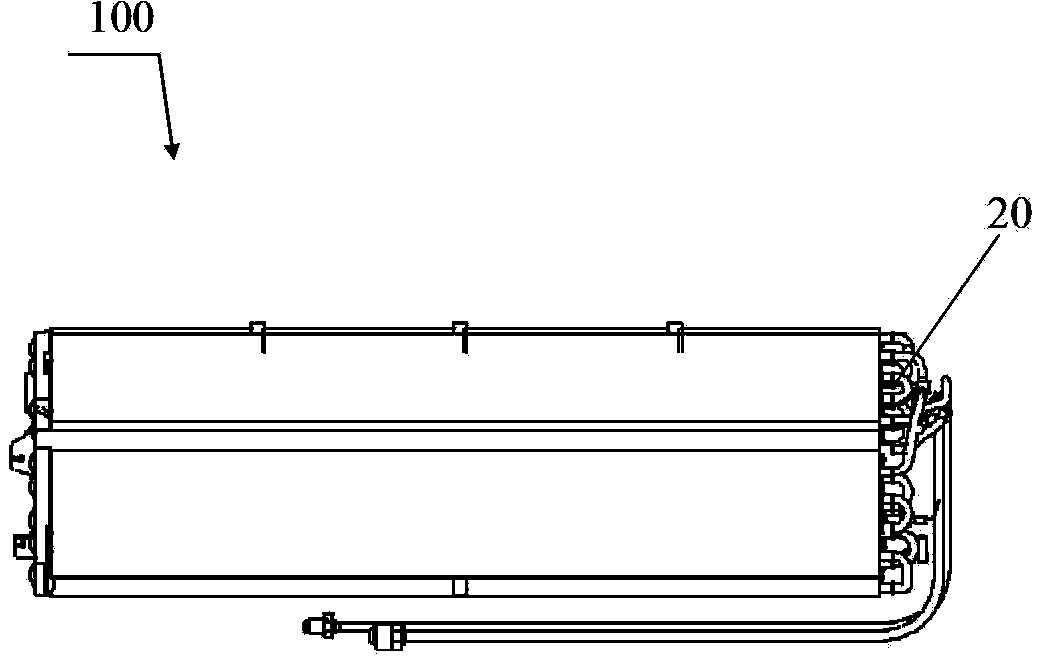
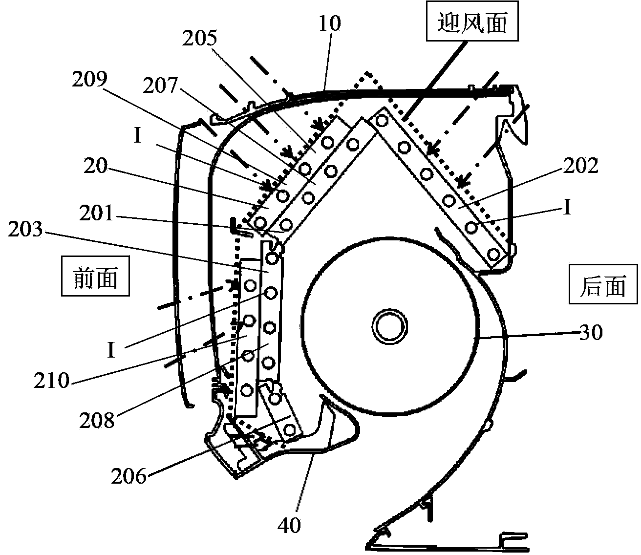
[0030] figure 2 It is a front view which shows the rough structure of the heat exchanger of the air conditioner which concerns on this invention. image 3 It is a cross-sectional view showing a schematic configuration of the air conditioner according to the first embodiment. Such as image 3 As shown, the indoor unit 100 includes an indoor unit main body 10 , a heat exchanger assembly 20 , a cross-flow blower 30 , and a water receiving tank 40 . The cross-flow blower 30 sucks air from a suction port located at the top of the indoor unit main body 10, and makes the sucked air flow through the heat exchanger assembly 20 for heat exchange, thereby sending out the air heated or cooled by the heat exchange from the delivery port. to indoors. The water receiving tank 40 is used for rec...

no. 2 Embodiment approach )

[0056] The air conditioner according to the second embodiment is different from the air conditioner according to the first embodiment in that the structure of the heat exchanger unit is different.

[0057] Figure 15 It is a perspective view which shows the schematic structure of the heat exchanger unit of the air conditioner which concerns on 2nd Embodiment. Such as Figure 15 As shown, the heat exchanger assembly 20' according to this embodiment includes a front heat exchanger 201' whose windward surface faces the front of the indoor unit and a rear heat exchanger 202 whose windward surface faces the back of the indoor unit.

[0058] That is, the front heat exchanger 201' includes a first-layer heat exchanger 203' as a layer closest to the cross-flow fan 30, a third-layer heat exchanger 205' as a layer closest to the windward side, and an intermediate layer. The second layer heat exchanger 204' between the first layer heat exchanger 203' and the third layer heat exchanger ...


PUM


Abstract

The invention relates to an air conditioner. The air conditioner comprises an indoor unit. In the indoor unit, a heat exchanger assembly is formed in the manner of surrounding a cross-flow supply fan. The heat exchanger assembly is composed of fin-tube-type heat exchangers and comprises the front heat exchanger with the air-facing side facing the front side of the indoor unit and the rear heat exchanger with the air-facing side facing the back side of the indoor unit. At least part of the front heat exchanger is formed by stacking M layers of heat exchanger bodies which are respectively provided with a row of heat conduction tubes, and the rear heat exchanger is formed by stacking N layers of heat exchanger bodies which are respectively provided with a row of heat conduction tubes, wherein M and N are natural numbers, and N is smaller than M. The innermost layer of heat exchanger body, closest to the supply fan, of the front heat exchanger is formed by bending fins into a plurality of segments, wherein heat conduction tubes penetrate into the fins. Through the structure, condensate water can be reliably led into a water pan and prevented from splashing.

Description

technical field [0001] The present invention relates to an air conditioner. Background technique [0002] For a long time, in the existing air conditioners, for example, Japanese Patent Laid-Open Publication No. Hei 9-264555 discloses that a heat exchanger assembly of an air conditioner includes a front heat exchanger 1 and a rear heat exchanger 2 , the front heat exchanger 1 and part of the rear heat exchanger 2 are one-column heat exchangers. By increasing the air supply volume, the performance degradation caused by the reduction of the heat transfer area is suppressed, and the performance of the heat exchanger is maintained. while reducing costs. However, in the existing air conditioner, there is no disclosure of any condensed water drainage structure, especially in the lower part of the front heat exchanger 1 due to the reduction in the number of rows, and it is formed independently from other parts, Therefore, the condensed water on the upper part of the front heat ex...

Claims


Application Information

Patent Timeline
Patent Type & Authority Applications(China)
IPC IPC(8): F24F1/00F24F13/30F24F13/22
Inventor 沈卓君柯峰
Owner PANASONIC CORP
Why Eureka
Try Eureka