A blasting method for concrete hollow columns

A concrete and hollow technology, applied in the field of blasting, can solve the problems affecting the quality of blasting holes, blasting without breaking concrete, leakage of blasting gas, etc., achieving high use efficiency, reducing the number of blasting holes, and good hole-forming quality. Effect

Active Publication Date: 2016-01-06
WUHAN BLASTING ENG
View PDF4 Cites 0 Cited by
  • Summary
  • Abstract
  • Description
  • Claims
  • Application Information

AI Technical Summary

Problems solved by technology

When drilling and blasting on this kind of column, because there is a hollow part in the concrete column, it will affect the quality of the blast hole during blasting and cause the leakage of blasting gas, which is not conducive to the uniform damage of the concrete material during drilling and blasting, and may easily cause explosion. Not broken or part of the concrete cannot be destroyed by blasting, and a large amount of blasting scatter is formed due to the change of the resistance line, resulting in blasting accidents

Method used


Image

  • A blasting method for concrete hollow columns
  • A blasting method for concrete hollow columns

Examples


Embodiment 1

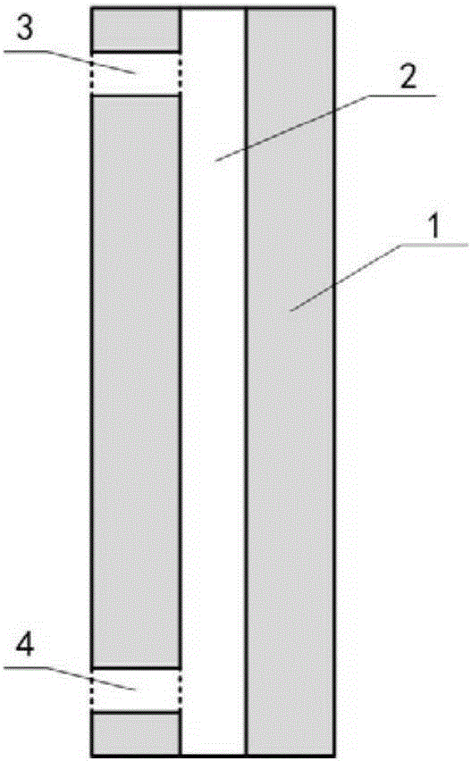
[0021] This embodiment provides a blasting method for a concrete hollow column, which is used for drilling and blasting demolition of a viaduct pier. During the drilling construction process, it was found that the center of the bridge pier is hollow and continuous cavity, so the blasting method of the present invention is adopted, which includes the following steps:

[0022] (1) drill top hole 3 at the top of concrete hollow column 1, top hole 3 to the hollow area 2 of concrete hollow column 1, pour water in hollow area 2, to determine the airtightness of the size of hollow area 2 and hollow area 2;

[0023] (2) Bottom hole 4 is drilled at the bottom of concrete hollow column 1. Bottom hole 4 reaches hollow area 2 of concrete hollow column 1. Water can wash sundries in hollow area 2, and finally drain water in hollow area 2. ;

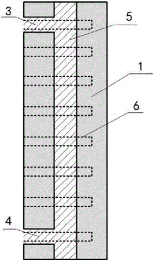
[0024] (3) Inject cement slurry 5 into the hollow area 2 through the top hole 3, and the cement slurry 5 is a mixture of water and cement. When the ...

Embodiment 2

[0027] The difference between this embodiment and embodiment 1 is that the hole diameters of the top hole 3 and the bottom hole 4 are 5 cm.

[0028] The present invention adopts grouting to repair the concrete hollow column 1, which is convenient and fast, and reduces the problem of drilling multiple blast holes due to the influence of the cavity, thus saving construction cost, saving engineering time, and improving construction efficiency; construction equipment and materials are relatively Common, easy to buy, rent and use, and has strong versatility; the repaired concrete hollow column 1 is drilled and drilled with good hole quality, the number of blast holes is significantly reduced, and the blasting efficiency is high; cement is injected into the cavity of the concrete hollow column 1 After the slurry 5 is solidified, it has good adhesion with the original concrete material, which is beneficial to the uniform crushing of the concrete hollow column 1 by explosive placement ...


PUM

PropertyMeasurementUnit
diameteraaaaaaaaaa

Abstract

The invention discloses a concrete hollow pillar blasting method, and belongs to the technical field of blasting. The method includes the following steps that (1) a top hole is drilled in the top of a concrete hollow pillar, a hollow area is formed from the top hole to the concrete hollow pillar, and water is poured into the hollow area; (2) a bottom hole is drilled in the bottom of the concrete hollow pillar, a hollow area is formed from the bottom hole to the concrete hollow pillar, and water in the hollow area is discharged; (3) cement slurry is poured into the hollow area through top hole, when the cement slurry reaches the position of the bottom hole, the bottom hole is plugged, and the hollow area is filled with the cement slurry;(4) when the cement slurry in the hollow area is solidified, hole drilling is conducted to the concrete hollow pillar according to the engineering design requirements, and blasting is conducted. According to the concrete hollow pillar blasting method, blasting quality is guaranteed when blasting is conducted to concrete pillars with hollow holes or continuous cavities.

Description

technical field [0001] The invention belongs to the technical field of blasting, in particular to a blasting method of a concrete hollow column. Background technique [0002] In demolition and blasting of buildings (structures), drilling and blasting on concrete columns is a commonly used method. In some projects, in order to save materials, reduce the weight of concrete columns, and speed up construction, hollow holes or continuous cavities are often designed in columns. When drilling and blasting on this kind of column, because there is a hollow part in the concrete column, it will affect the quality of the blast hole during blasting and cause the leakage of blasting gas, which is not conducive to the uniform damage of the concrete material during drilling and blasting, and may easily cause explosion. Not broken or part of the concrete cannot be destroyed by blasting, and a large amount of blasting scatter is formed due to the change of the resistance line, resulting in b...

Claims


Application Information

Patent Timeline
Patent Type & Authority Patents(China)
IPC IPC(8): F42D3/02E04G23/08
Inventor 谢先启贾永胜刘昌邦王洪刚姚颖康
Owner WUHAN BLASTING ENG
Why Eureka
Try Eureka