Punching and Forming Lubrication System and Lubricant Retention Matrix

a lubrication system and lubricant technology, applied in the field of forming and punching, can solve the problems of deterioration and failure of punches, no satisfactory system for lubricating or retaining lubricant within the casing of such a punch assembly, etc., to reduce or prevent stripping problems in punching or forming operations, improve hole quality, and prolong the effect of punch li

Inactive Publication Date: 2013-02-28
MATE PRECISION TOOLING
View PDF20 Cites 10 Cited by
  • Summary
  • Abstract
  • Description
  • Claims
  • Application Information

AI Technical Summary

Benefits of technology

[0006]It is therefore an important objective of the invention to keep wear of parts in check from the beginning to thereby insure the life of the punch or forming tool.
[0007]Another object is to reduce or prevent a stripping problem in punching or forming operations.
[0008]An additional object is to eliminate the need to add lubrication to the bottom or top of a metal sheet or other workpiece.
[0009]A still further object is to help keep debris from building up on the punch point, to create better and more consistent punch forms, to improve hole quality, to extend punch life at a relatively low cost and to prevent debris from entering the system.

Problems solved by technology

Heretofore, no satisfactory system has been provided for lubricating or retaining lubricant within the casing of such a punch assembly.
The improvements provided by the inventors are particularly important because once a punch starts to wear, many of the adverse conditions noted above progress rapidly causing punch deterioration and failure.

Method used


Image

  • Punching and Forming Lubrication System and Lubricant Retention Matrix
  • Punching and Forming Lubrication System and Lubricant Retention Matrix
  • Punching and Forming Lubrication System and Lubricant Retention Matrix

Examples


example 1

Baseline (Without Matrix or Lubrication)

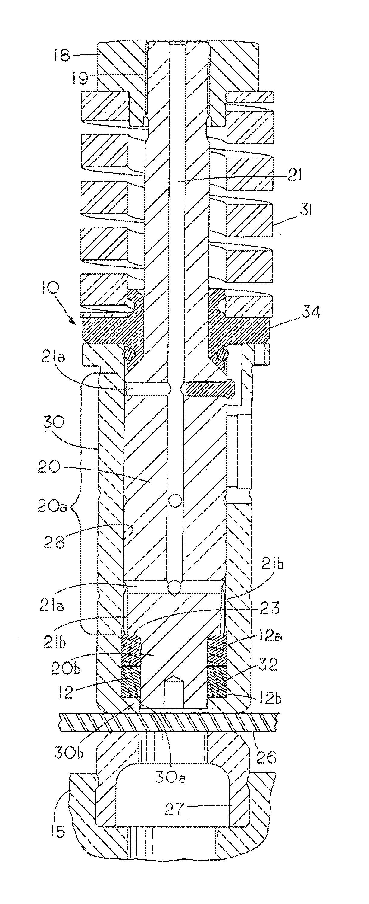
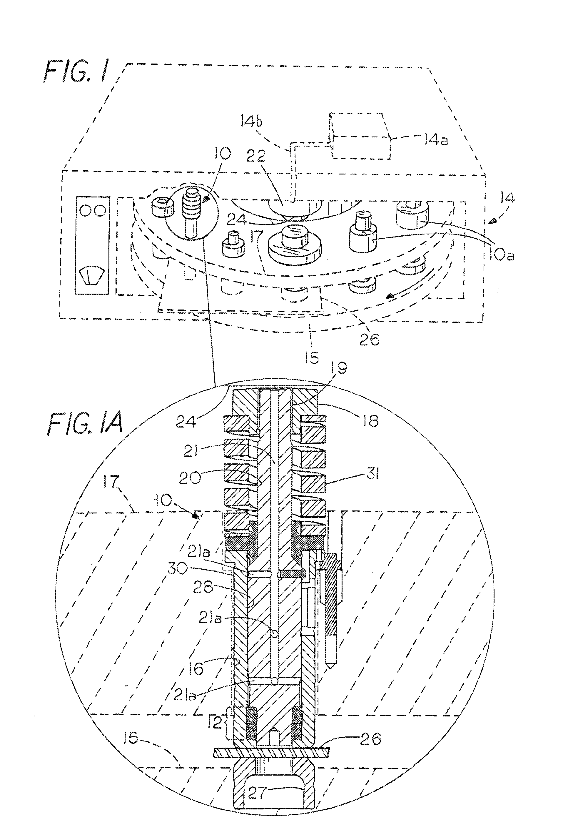
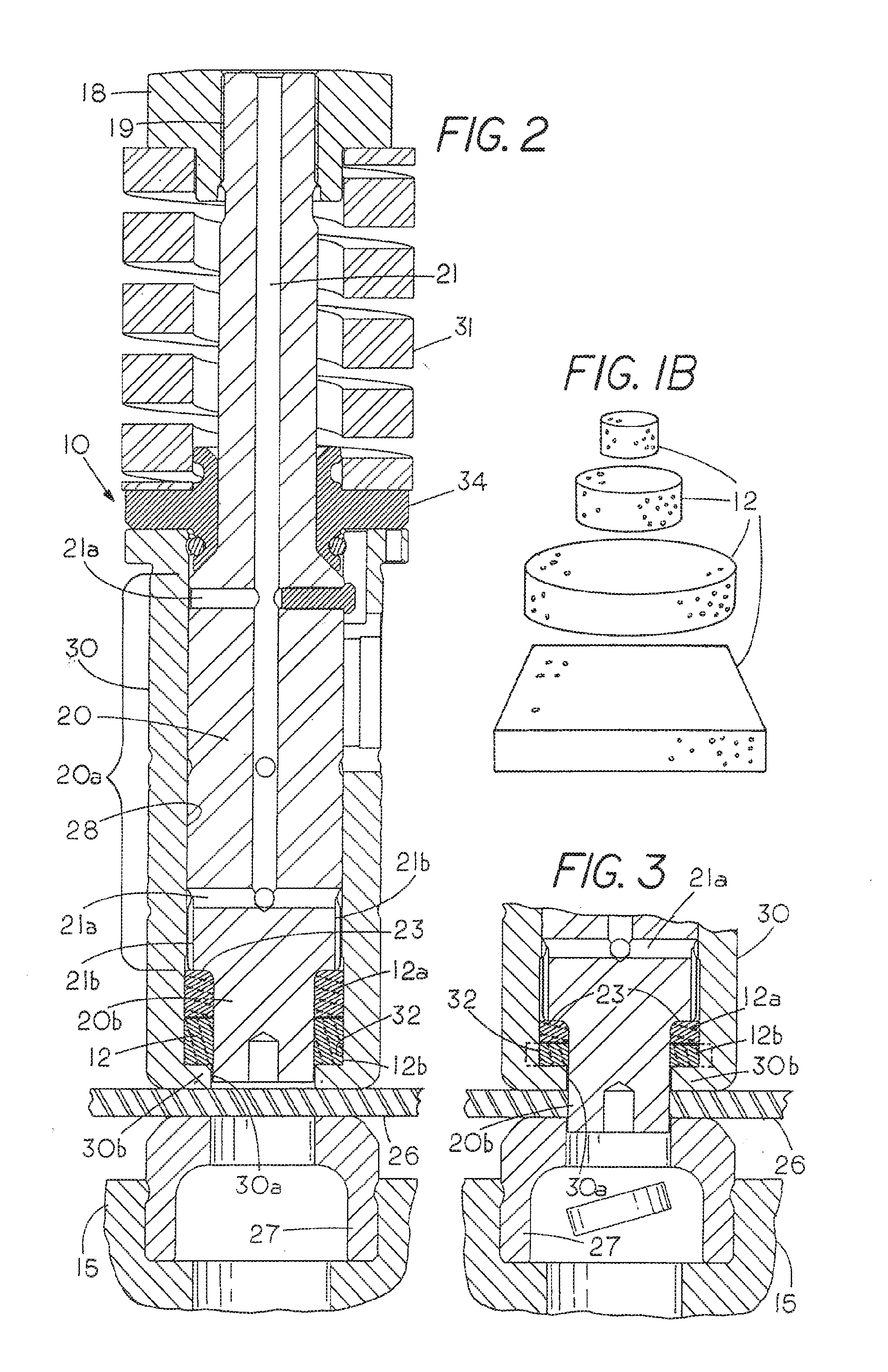
[0053]The punching system generally as shown in FIGS. 2 and 3 and having a punch with a diameter of 0.156″ and a die with 0.012″ clearance was used to punch 0.125″ thick 2024 T3 Aluminum sheet at speeds of 250 to 300 hits per minute with no matrix or lubrication present in the punch to material interface. Punch point galling started after 50 hits followed by punch failure before 1,050 hits. Failure was considered to constitute a growth of the punch point to +0.002 inch larger than the start diameter of 0.156″.

example 2

Invention

[0054]A matrix of polyether foam produced by the Foamex Co. of Eddystone, Pa. with an open cell structure having 80 pores per inch, 1.35″ in diameter and 0.8″ thick with a 1.15 cubic inch volume was placed over the punch point of Example 1 and saturated with 4.5 cc of Mobil DTE-25 hydraulic fluid. The punch assembly as in FIGS. 1-3 having a punch point diameter of 0.156″, a die with 0.012″ clearance was used to punch 0.125″ thick 2024 T3 Aluminum sheet at speeds of 250 to 300 hits per minute while compressing the matrix 50% to a height of 0.400″. The punch point was evaluated for galling after every 525 hits with absolutely no signs galling following the completion of the test at 6800 hits. In comparison to Example 1, the punch was projected to last a minimum of 6.5 times longer. This was based on a calculated product failure at 6800 hits. In reality no signs of galling were found to be present after 6800 hits so the life could theoretically be expected to be infinite as lo...


PUM

PropertyMeasurementUnit
diameteraaaaaaaaaa
volumeaaaaaaaaaa
volumeaaaaaaaaaa

Abstract

A punch element is mounted for sliding movement in the guide sleeve or casing with the punch point at its lower end for forming or punching a workpiece. A stripper element is located at the lower end of the guide sleeve which defines the casing of the punch assembly, and the stripper element has an opening aligned with the punch point through which the punch point passes to engage the workpiece. A matrix placement chamber is provided within the casing between the punch point and the guide sleeve so as to at least partially surround the punch point and at least one flexible lubrication matrix body is contained in the matrix placement chamber inside the housing. The matrix which is enclosed entirely within the casing of the unitary punch assembly in which the punch reciprocates comprises an integral porous elastic multi-cellular polymeric body containing a multiplicity of hollow communicating cells adapted to hold a lubricant in fluid communication with the sidewalls of at least the point of the punch and in a preferred form completely surrounds the punch point. The lubrication matrix can also hold a cleaning agent or an abrasive in particulate form.

Description

FIELD OF THE INVENTION [0001]This invention relates to punching and forming, and more particularly to an improved lubrication system for a punching or forming assembly adapted for use in punch press tooling including automated thick turret punch press tooling.BACKGROUND OF THE INVENTION [0002]Punch failure has several causes, the main factors being excess heat, fracture and galling. Excessive heat will anneal the punch point and tend to soften it. This contributes to an easier breakdown of the edge. Investigations carried out in developing the present invention also show that the lubrication does not consistently cover the punch point. If provided consistently, the lubrication reduces heat buildup and can extend the life of a punch point. Punch fracture is a condition in which metal chips away from the cutting edge of the punch. Lubrication will help this mode of failure but only minimally. Galling is a condition in which the punch point collects material being punched or formed. As...

Claims


Application Information

Patent Timeline
Patent Type & Authority Applications(United States)
IPC IPC(8): B21D45/08B23P11/00B21D37/18B26D7/08B26D7/12
CPCB21D37/18Y10T29/49833B26D7/088Y10T83/215Y10T83/303
Inventor WINDINGSTAD, RONALD C.
Owner MATE PRECISION TOOLING
Why Eureka
Try Eureka