Drill

a drill and drill bit technology, applied in the field of drill bit, can solve the problems of difficult to increase the feed speed reduce the boring time of the drill bit, and wear of the cutting edge may progress relatively quickly, so as to improve the service life and prevent the increase of the feed speed required to compensate the retraction of the maximum diameter position. the effect of reducing the number of holes

Active Publication Date: 2014-05-27
SUBURU CORP +1
View PDF50 Cites 9 Cited by
  • Summary
  • Abstract
  • Description
  • Claims
  • Application Information

AI Technical Summary

Benefits of technology

[0007]In light of the situations, the present invention provides a drill partly having four cutting edges, the drill being capable of improving the quality of holes to be machined and extending the service life of the drill as compared with a two-edge drill, by effectively introducing the four cutting edges without any trouble while attaining high cutting performance like the two-edge drill.
[0010]With the aspect of the present invention, the main cutting edges performs cutting first, the cutting range of the auxiliary cutting edges for a hole to be machined is widened as wear of the main cutting edges progresses, and the main cutting edges also effectively perform cutting in the cutting range of the auxiliary cutting edges. Thus, cutting with the four cutting edges including the main cutting edges and the auxiliary cutting edges can be attained. The maximum diameter position is retracted as the wear progresses. The cutting range of the four cutting edges including the main cutting edges and the auxiliary cutting edges is widened from the initial maximum diameter position toward the distal and proximal ends of the drill as the wear progresses.
[0012]In addition, since the four cutting edges are introduced at the maximum diameter position as the wear progresses, the further progress of the wear which causes the maximum diameter position to be further retracted can be restricted as compared with the two-edge drill. The service life can be increased. Further, the feed speed required to compensate the retraction of the maximum diameter position can be prevented from increasing.
[0013]Accordingly, with the aspect of the invention, the high cutting performance like the two-edge drill can be attained by the main cutting edges in the cutting range of only the main cutting edges. Cutting with the four cutting edges including the main cutting edges and the auxiliary cutting edges can be smoothly introduced without any trouble as the wear progresses. Then, finishing with the four cutting edges can be performed. Thus, the finishing quality of holes to be machined can be improved and the service life of the drill can be extended as compared with the two-edge drill while attaining the high cutting performance like the two-edge drill.
[0014]Thus, with the drill according to the aspect of the present invention, a hole with the high finishing quality can be machined in a short time, and a larger number of holes can be repeatedly machined.

Problems solved by technology

However, since the two-edge drill has the relatively small number of cutting edges, wear of the cutting edges may progress relatively quickly.
Thus, it may be difficult to increase the feed speed of the drill and to decrease the boring time with the drill.

Method used


Image

  • Drill
  • Drill
  • Drill

Examples


Embodiment Construction

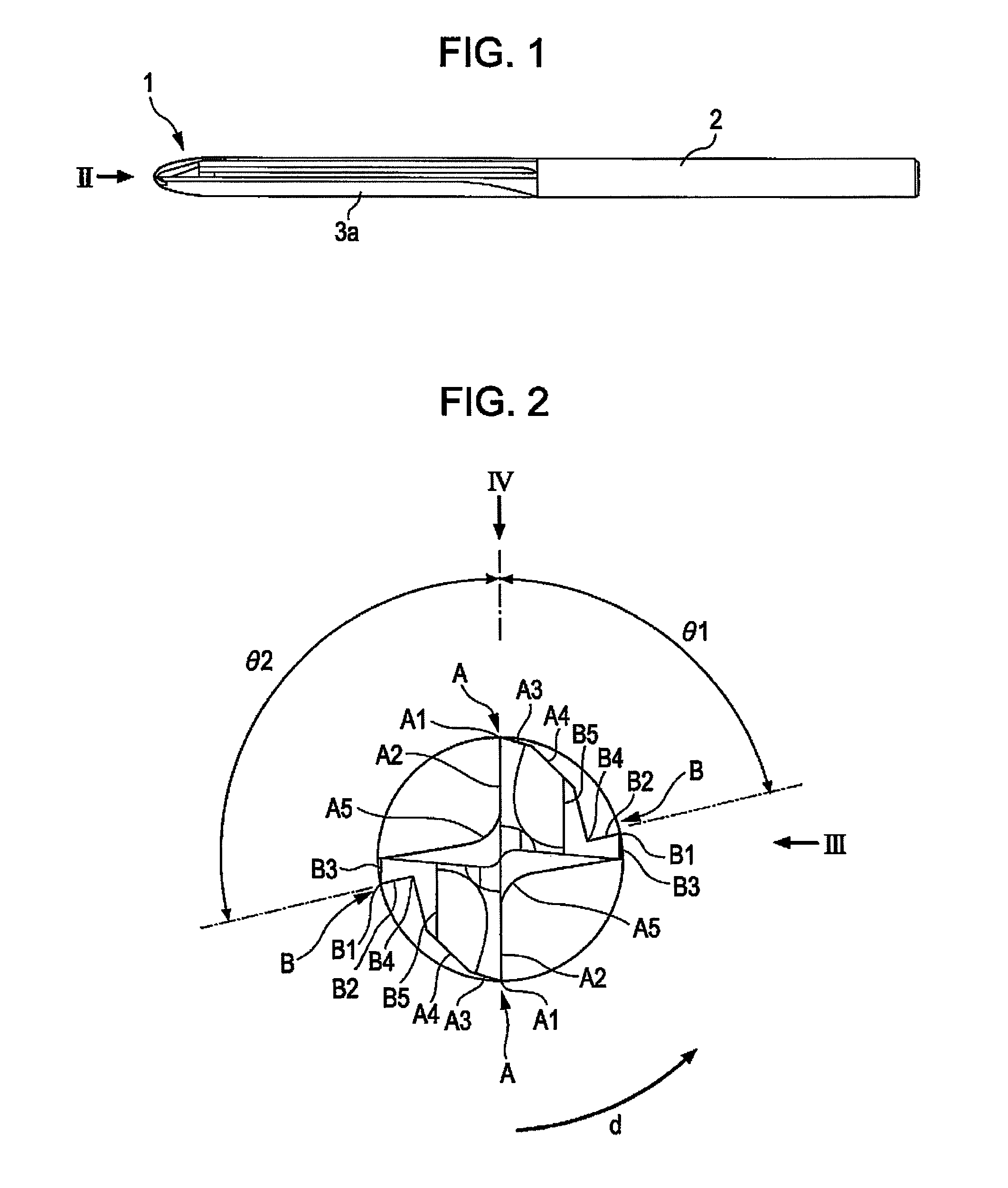
[0023]Hereinafter, an embodiment of the present invention will be described with reference to the attached drawings. The embodiment is merely an example of the present invention, and hence the present invention should not be limited to the embodiment.

[0024]Referring to FIG. 1, a drill of this embodiment includes a cutter edge section 1 and a shank section 2. Two straight V-grooves 3a are formed between the cutter edge section 1 and the shank section 2.

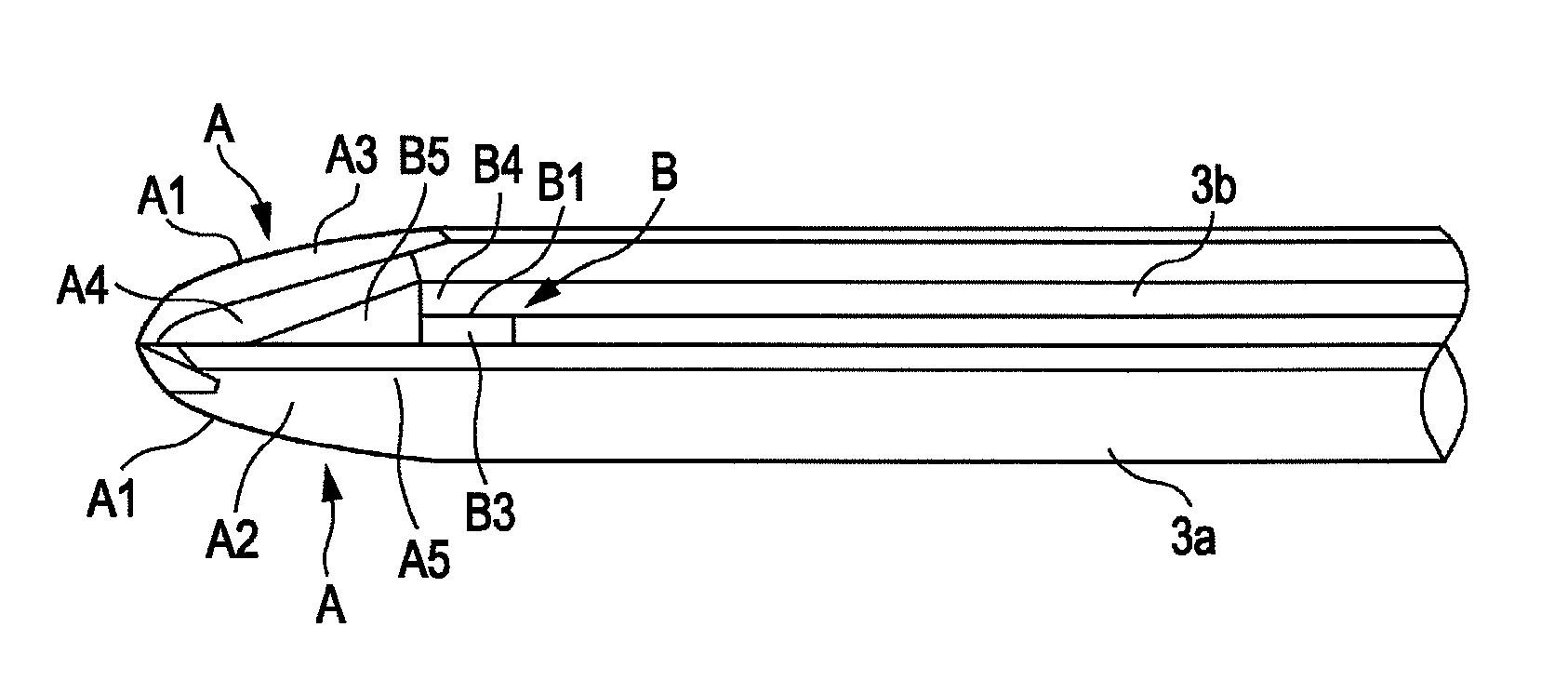
[0025]Referring to FIG. 2, the cutter edge section 1 includes a pair of main cutting edges A symmetrically provided with respect to the axis of the drill, and a pair of auxiliary cutting edges B symmetrically provided with respect to the axis of the drill.

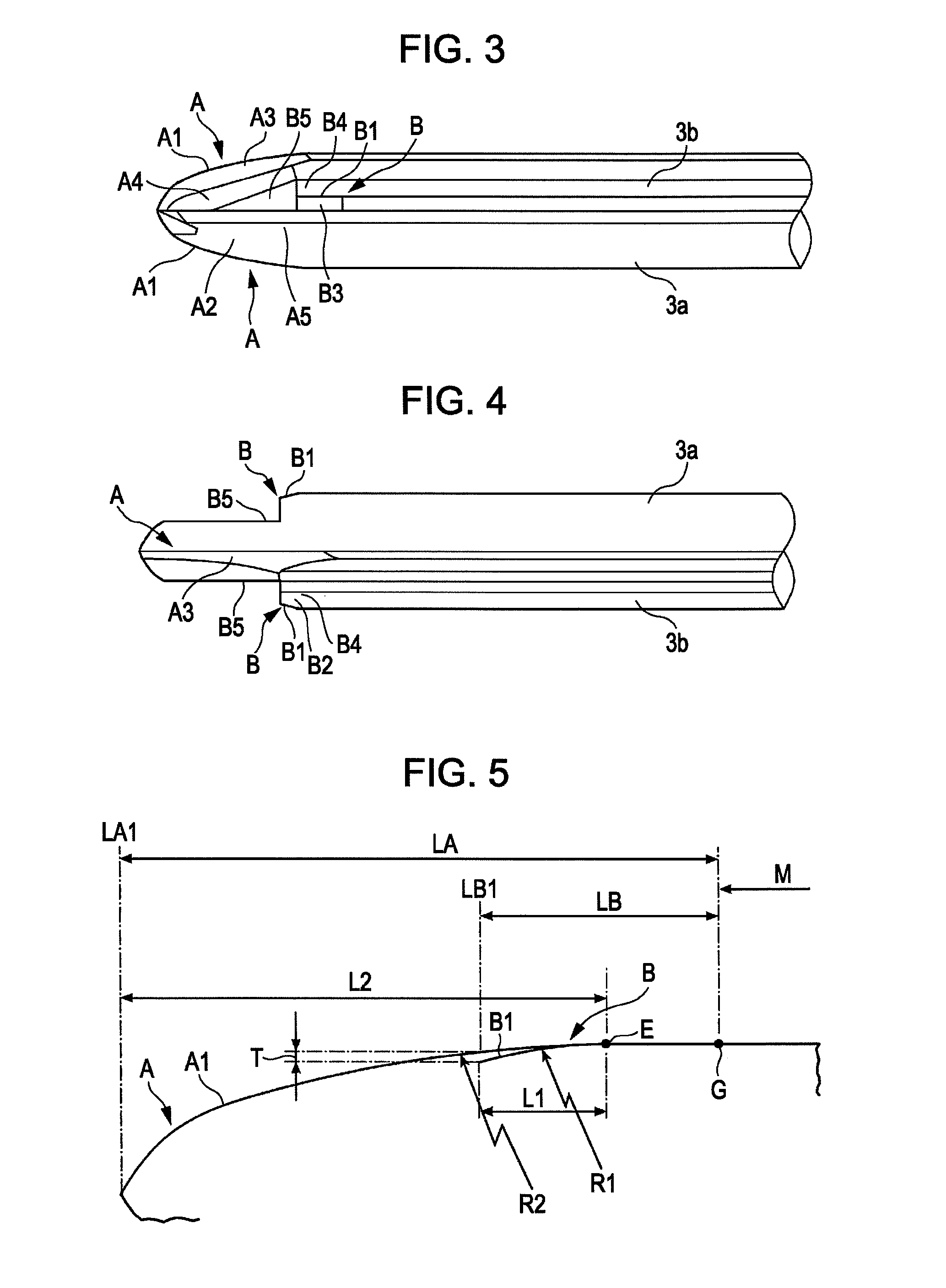
[0026]Referring to FIG. 2, arrow d indicates the rotation direction of the drill during cutting. The main cutting edges A each have a rake face A2 and a second relief face A3 that are adjacent to one another at a ridgeline A1. A third relief face A4 is formed continuously from the sec...


PUM

PropertyMeasurementUnit
angleaaaaaaaaaa
relative angleaaaaaaaaaa
diameteraaaaaaaaaa

Abstract

A drill includes a pair of main cutting edges extending from a distal portion of the drill to a position close to a proximal end of the drill to entirely define a two-edge configuration, and a pair of auxiliary cutting edges extending between positions at the distal and proximal sides of a maximum diameter position to partly define a four-edge configuration. A ridgeline of each auxiliary cutting edge is located within an angle smaller than 90° from a ridgeline of the corresponding main cutting edge toward the rear in a rotation direction of the drill. The point angle of the auxiliary cutting edges increases at a higher rate than the point angle of the main cutting edges in a predetermined range from the maximum diameter position toward a distal end of the drill.

Description

CROSS-REFERENCES TO RELATED APPLICATIONS[0001]The present application claims priority from Japanese Patent Application No. 2009-061009 filed on Mar. 13, 2009, and is hereby incorporated by reference in its entirety.BACKGROUND OF THE INVENTION[0002]1. Field of the Invention[0003]The present invention relates to a drill that partly has four cutting edges.[0004]2. Description of the Related Art[0005]A drill is generally used as a boring tool. A two-edge drill is frequently used (for example, see Japanese Unexamined Patent Application Publication No. 2008-36759). The two-edge drill has a relatively small number of cutting edges, and hence the two-edge drill can have large grooves. Thus, machining dust is efficiently discharged. As long as the machining dust is efficiently discharged, the feed speed of the drill can be increased, and the boring time with the drill can be decreased. However, since the two-edge drill has the relatively small number of cutting edges, wear of the cutting edg...

Claims


Application Information

Patent Timeline
Patent Type & Authority Patents(United States)
IPC IPC(8): B23B51/02
CPCB23B2251/204B23B51/00B23B2220/44B23B2251/282B23B2220/24B23B2251/14Y10T408/909Y10T408/9095Y10T408/906
Inventor SAITO, MANABUNAKAHATA, TATSUOTAKAHASHI, HIDEHARUTSUCHIYA, JUNJIHASHIMOTO, EIJIHIGASHIWAKI, HIROFUMI
Owner SUBURU CORP
Why Eureka
Try Eureka