
Device for measuring rotational inertia and friction moment of ball screw

A technology of ball screw and friction torque, applied in the direction of measuring device, static/dynamic balance test, torque measurement, etc., can solve the problem of no ball screw, etc., achieve reliable measurement results, simple structure, and improve sensitivity Effect

Inactive Publication Date: 2014-07-02
TSINGHUA UNIV
View PDF4 Cites 26 Cited by
  • Summary
  • Abstract
  • Description
  • Claims
  • Application Information

AI Technical Summary

Problems solved by technology

In addition, the existing friction torque dynamic measuring instrument and other instruments also have many deficiencies in terms of function and accuracy, and there is no effective measuring device for measuring the friction torque of the ball screw.

Method used

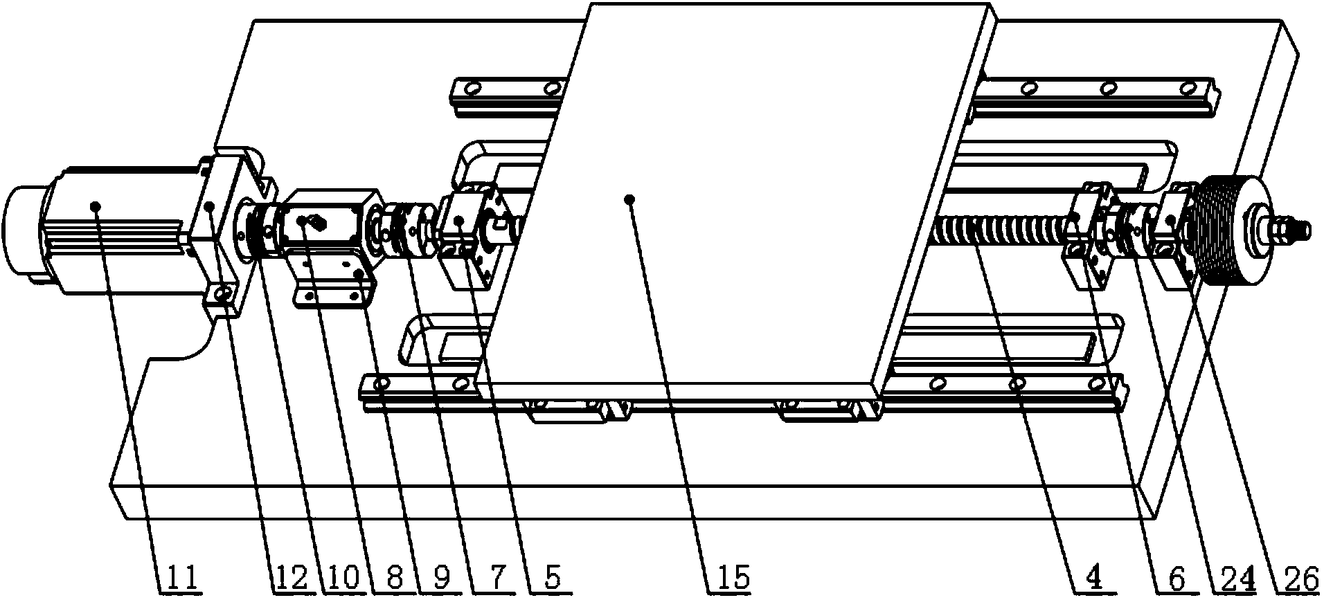
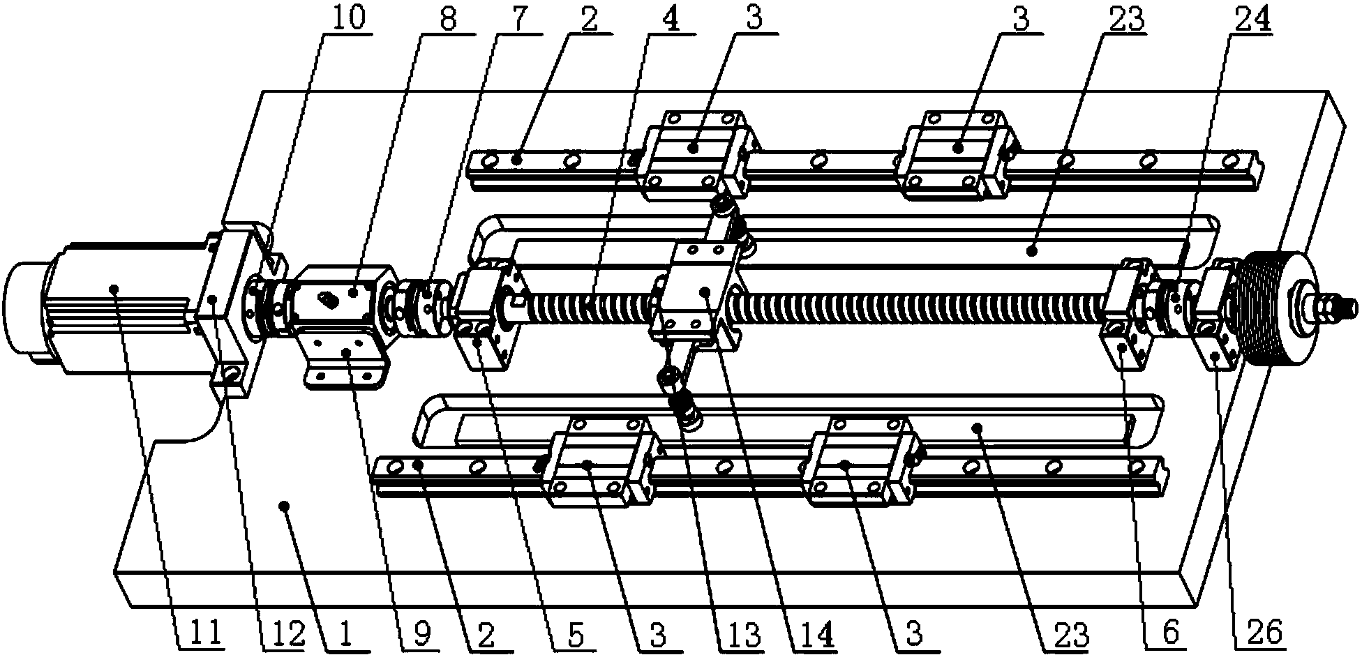

Image

  • Device for measuring rotational inertia and friction moment of ball screw
  • Device for measuring rotational inertia and friction moment of ball screw
  • Device for measuring rotational inertia and friction moment of ball screw

Examples


Embodiment Construction

[0014] The present invention will be described in detail below in conjunction with the accompanying drawings and embodiments.

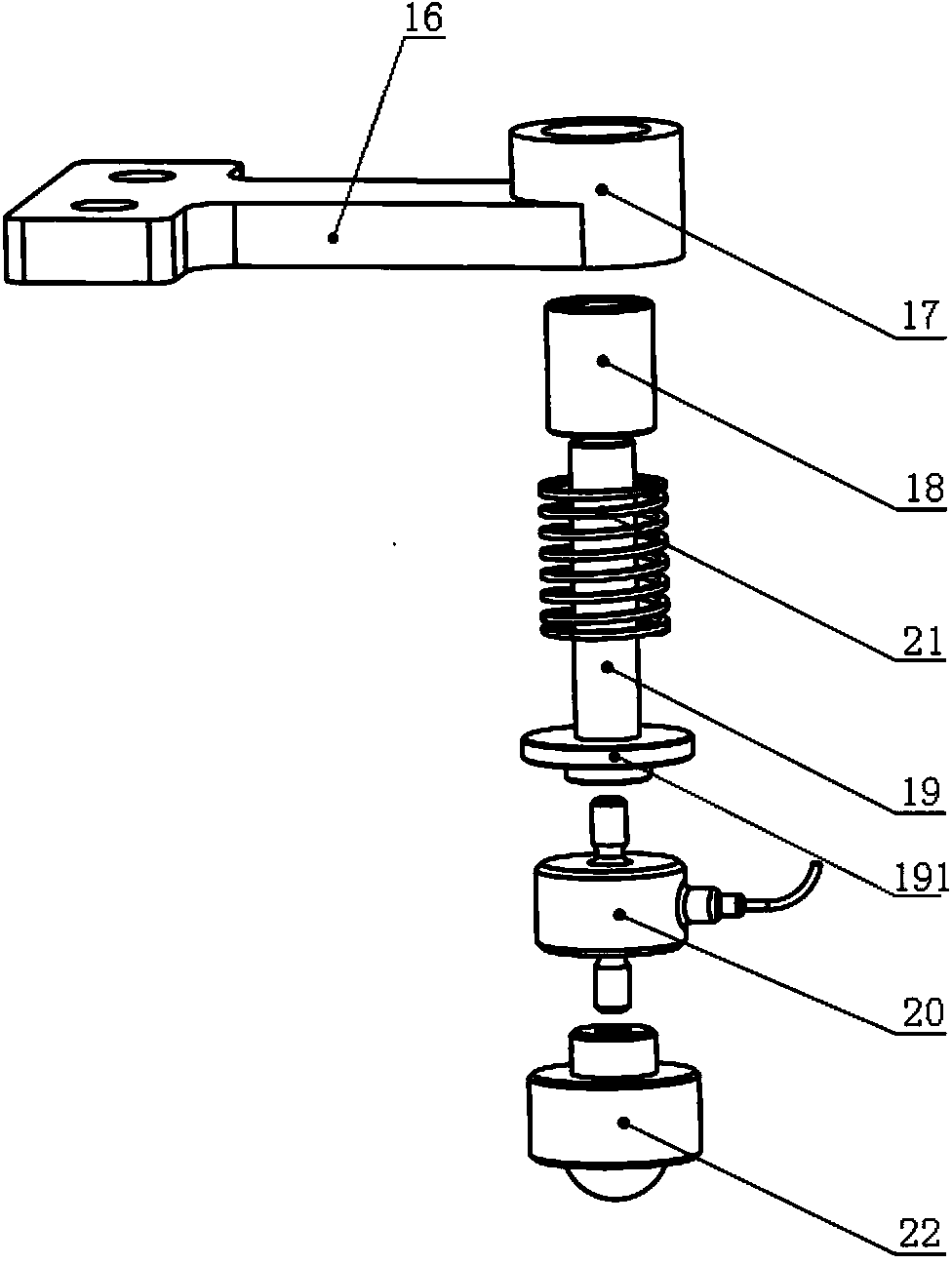
[0015] Such as figure 1 , figure 2 As shown, the present invention includes a bottom plate 1, two linear guide rails 2 are arranged in parallel at intervals on the top surface of the bottom plate 1, and two sliders 3 are respectively arranged on each linear guide rail 2. In the middle of the two linear guide rails 2, a ball screw 4 is installed in parallel. One end of the ball screw 4 is rotatably supported on a fixed support seat 5, and the other end is rotatably supported on a floating support seat 6 (a ball screw here). Conventional setting when the bar 4 is installed, that is, in the two support seats, one of them is immovable with the ball screw 4 in the axial direction, and the other is slidable with the ball screw 4 in the axial direction). Both the fixed support base 5 and the floating support base 6 are fastened to the bottom plate 1 . On...


PUM


Abstract

The invention relates to a device for measuring rotational inertia and friction moment of a ball screw. The device comprises a bottom plate, two linear guide rails, the ball screw, a torque sensor, a servo motor, a mobile platform and two friction moment measuring mechanisms. Each linear guide rail is provided with two sliding blocks. The two ends of the ball screw are supported by the part, located between the two linear guide rails, of the bottom plate in a rotary mode through a fixed supporting base and a floating supporting base. One end of the torque sensor is connected with the end, supported by the fixed supporting seat, of the ball screw through a coupler. An output shaft of the servo motor is connected with the torque sensor through a coupler. The two friction moment measuring mechanisms are arranged on the two sides of a screw nut base respectively. Each friction moment measuring mechanism comprises a cantilever. A connecting sleeve is arranged at the tail end of each cantilever. Each connecting sleeve is connected with a sliding bar through a vertical linear bearing. The other end of each sliding bar is connected with a pressure sensor. Each sliding bar is sleeved with a spring. The bottom of each pressure sensor is connected with a universal ball. The bottom of each universal ball makes contact with a linear slab which is parallel to the ball screw. The linear slabs are tightly connected to the bottom plate.

Description

technical field [0001] The invention relates to a measuring device, in particular to a measuring device for the moment of inertia and friction moment of a ball screw. Background technique [0002] The ball screw is the key functional part of the CNC machine tool, and its quality directly affects the overall performance of the CNC machine tool. The performance requirements are getting higher and higher, and the ball screw is required to have the advantages of high guiding transmission efficiency, stable transmission, good synchronization, good precision retention, and high reliability. Since the performance of the ball screw directly affects the positioning accuracy and processing quality of the CNC machine tool, it should be ensured that it has excellent performance during the process of manufacturing and using the ball screw, and at the same time it is necessary to conduct high-precision inspections of the relevant performance parameters of the ball screw. , Efficient and ...

Claims


Application Information

Patent Timeline
Patent Type & Authority Applications(China)
IPC IPC(8): G01M13/02G01M1/10G01L3/00
Inventor 李铁民姜峣杜云松张亮亮吴军
Owner TSINGHUA UNIV
Learn More