Accelerometer

An accelerometer and acceleration technology, applied in the direction of measurement of acceleration, speed/acceleration/shock measurement, measurement device, etc., can solve the problem of restricting the performance of capacitive high-range micromechanical accelerometer, large deformation of sensor sensitive mass, and inability to resist overload. Satisfaction and other problems, to achieve the effect of increasing the allowable variation range, improving the measurement accuracy, and improving the influence of cross-axis coupling

Active Publication Date: 2014-07-02
TSINGHUA UNIV
View PDF7 Cites 0 Cited by
  • Summary
  • Abstract
  • Description
  • Claims
  • Application Information

AI Technical Summary

Problems solved by technology

However, these two accelerometers are out-of-plane sensitive forms with variable gaps, and their anti-overload capability cannot meet some special requirements.
[0005] Existing high-range micromachined accelerometers generally work in an open-loop state. When high-amplitude acceleration is input, the deformation of the sensor’s sensitive mass is large. The variable-gap capacitance sensing method of the above two accelerometers will cause the full-scale linearity to deteriorate.
Existing high-range micromachined accelerometers have low sensitivity due to limitations in range and resonant frequency
These problems have restricted the further improvement of the performance of capacitive high-range micro-machined accelerometers

Method used


Image

  • Accelerometer
  • Accelerometer
  • Accelerometer

Examples


Embodiment Construction

[0034] The implementation of the present invention will be described in detail below in conjunction with the accompanying drawings and examples, so as to fully understand and implement the process of how to apply technical means to solve technical problems and achieve technical effects in the present invention. It should be noted that, as long as there is no conflict, each embodiment and each feature in each embodiment of the present invention can be combined with each other, and the formed technical solutions are all within the protection scope of the present invention.

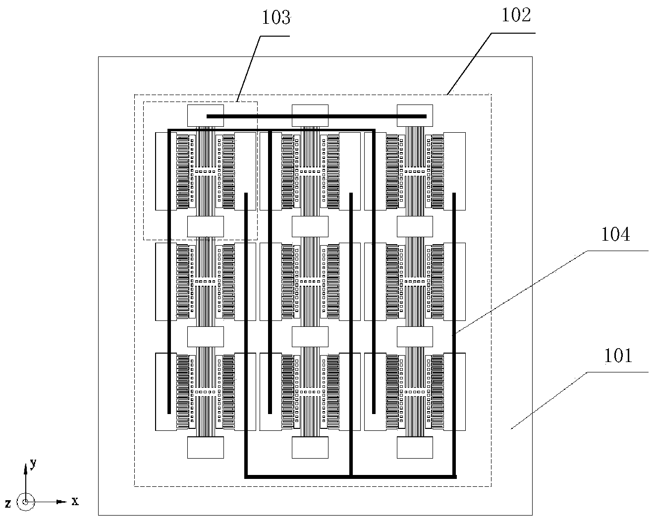
[0035] figure 1 A structural diagram of the accelerometer provided according to this embodiment is shown.

[0036] Such as figure 1 As shown, in this embodiment, the accelerometer includes a substrate 101 and an accelerometer body 102 fixed on the substrate 101 . Wherein, the accelerometer main body 102 includes several sensitive units 103 connected in parallel. The parallel connection of multiple sensiti...


PUM


Abstract

The invention discloses an accelerometer which comprises a substrate and an accelerometer body fixed to the substrate. The accelerometer body comprises a plurality of parallel-connection sensing units, wherein each sensing unit comprises a mass block, a first fixed base and a tooth set, two longitudinal ends of the mass blocks are fixedly connected with the substrate through elastic pieces, the elastic pieces are arranged at two longitudinal ends of the mass blocks, the first ends of the mass blocks are fixedly connected with the substrate, the first fixed bases are arranged on transverse side faces of the mass blocks and are fixedly connected with the substrate, the tooth sets are arranged between the first fixed bases and the mass blocks, and each tooth set comprises a plurality of fixed teeth which are fixed to the first fixed bases, extend in the transverse direction and are spaced from one another in the longitudinal direction, and a plurality of movable teeth which are staggered between the fixed teeth and fixed to the mass blocks. Through the parallel connection of the sensing units, the sensitivity and resolution are improved, and the nonlinearity of acceleration full range is improved through capacitance changes of a variable area.

Description

technical field [0001] The invention relates to the technical field of micromechanical inertial instruments, in particular to an accelerometer. Background technique [0002] High-range micromachined accelerometers are widely used in fields such as explosion and shock testing. In these applications, the magnitude of the instantaneous shock acceleration may exceed 100,000g, and the shock duration is very short (usually within a few hundred microseconds), so the accelerometer has a high range and resonant frequency. [0003] The capacitive silicon micromachined accelerometer has unique advantages such as mature technology, high frequency response, low power consumption, small temperature drift and strong overload resistance. It can meet the requirements of high range and high resonance frequency. Large high-g accelerometer type. [0004] At present, there are two main structural forms of capacitive high-range silicon micromachined accelerometers: the torsional structure of th...

Claims


Application Information

Patent Timeline
Patent Type & Authority Applications(China)
IPC IPC(8): G01P15/125
Inventor 陶永康刘云峰董景新
Owner TSINGHUA UNIV
Why Eureka
Try Eureka