Fiber Coupler

A fiber optic coupling and connector technology, applied in the field of fiber optic coupling connectors, can solve problems such as improvement, limitation of the number of optical fiber arrangements, and unfavorable optical signal transmission speed, etc., to achieve the effect of increasing the number of arrangements

Active Publication Date: 2017-06-20
FOXCONN (KUNSHAN) COMPUTER CONNECTOR CO LTD +1
View PDF5 Cites 0 Cited by
  • Summary
  • Abstract
  • Description
  • Claims
  • Application Information

AI Technical Summary

Problems solved by technology

When in use, each optical fiber corresponds to a lens arranged on the left end face, so that the number of optical fibers is limited, which is not conducive to the improvement of optical signal transmission speed

Method used


Image

  • Fiber Coupler
  • Fiber Coupler
  • Fiber Coupler

Examples


Embodiment Construction

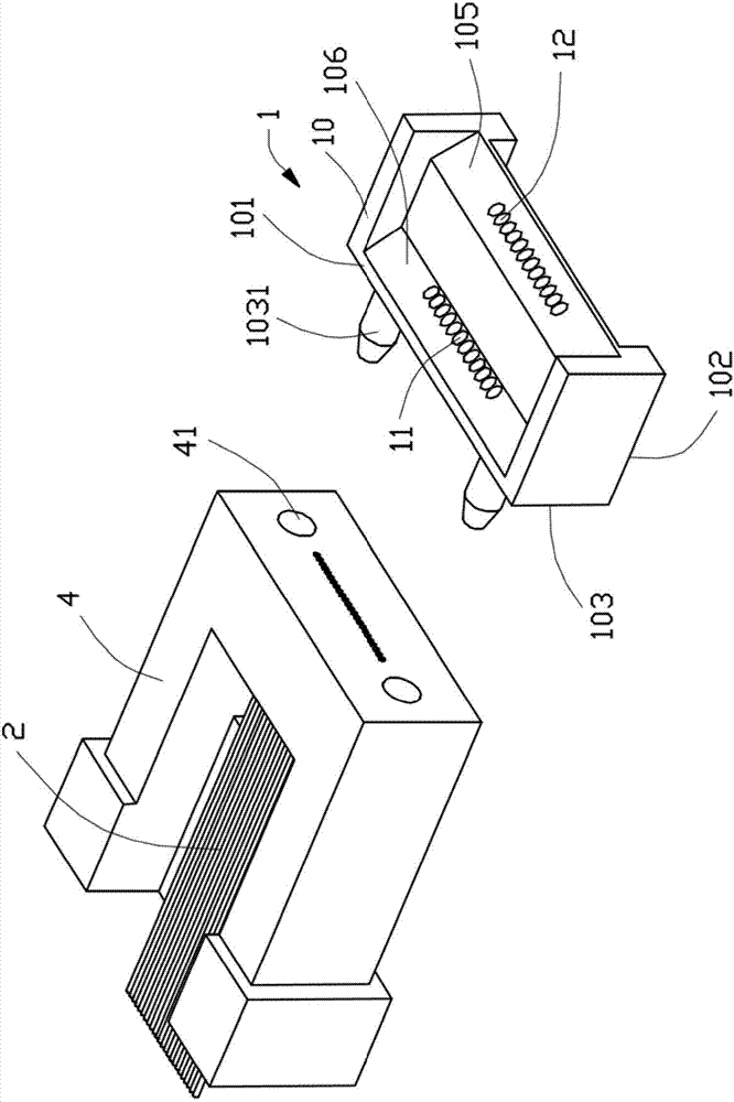
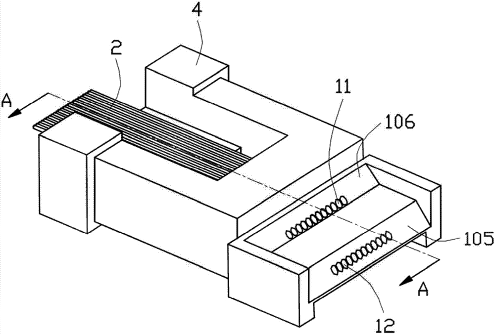
[0023] see figure 1 As shown, the optical fiber coupling connector 1 of the present invention is used for docking with the optical fiber 2 to transmit optical signals. Several second lenses 12 located in the second row. Several optical fibers 2 are fixed on the fixing base 4, and a pair of positioning holes 41 are arranged on the fixing base 4.

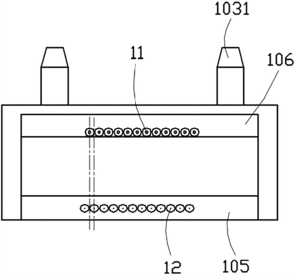
[0024] The plastic body 10 includes an upper surface 101 and a lower surface 102 that are parallel to each other, a front surface 103 that connects the upper surface 101 and the lower surface 102 and is perpendicular to the upper surface 101 and the lower surface 102, and forms an included angle with the front surface 103 and the lower surface 102. The first slope 106 and the second slope 105. The first inclined plane 106 and the second inclined plane 105 are arranged forward and backward. The included angle between the first slope 106 and the lower surface 102 is 45°. The first lens 11 is disposed on the first slope 106 , and the...


PUM


Abstract

An optical fiber coupling connector, which is used to connect with an optical fiber to transmit optical signals, the optical fiber coupling connector includes a plastic body and a plurality of first lenses in the first row and a plurality of second lenses in the second row arranged in the plastic body. The lens, the plastic body includes a lower surface, an upper surface opposite to the lower surface, a front surface connecting the upper surface and the lower surface, a first slope and a second slope forming an angle with the lower surface, and the first slope and the second slope face forward and backward Setting, several first lenses are arranged on the first inclined surface, several second lenses are arranged on the second inclined surface, the first lenses located in the first row and the plurality of second lenses located in the second row are arranged on the lower surface of the plastic body The projections are all misplaced and arranged, which increases the arrangement number of butt-connected optical fibers.

Description

[0001] 【Technical field】 [0002] The invention relates to an optical fiber coupling connector, in particular to an optical fiber coupling connector which increases the number of optical fiber arrays. [0003] 【Background technique】 [0004] Chinese Patent Publication No. 102667565A discloses an existing optical fiber coupling connector, which includes a lens array body and several lenses arranged on the lens array body. The main body of the lens array is provided with a left end surface facing the optical fiber and a lower end surface facing the photoelectric conversion device, and several lenses are respectively arranged on the left end surface and the lower end surface. When in use, each optical fiber corresponds to a lens arranged on the left end surface, so that the number of optical fibers is limited, which is not conducive to the improvement of the transmission speed of optical signals. [0005] In view of this, it is indeed necessary to improve the existing optical fib...

Claims


Application Information

Patent Timeline
Patent Type & Authority Patents(China)
IPC IPC(8): G02B6/32
Inventor 张俊毅刘家豪
Owner FOXCONN (KUNSHAN) COMPUTER CONNECTOR CO LTD
Why Eureka
Try Eureka