Chip carrying winding

A chip and tape technology, used in electrical components, electrical solid devices, circuits, etc.

Inactive Publication Date: 2007-02-28
CHIPMOS TECH INC
View PDF0 Cites 0 Cited by
  • Summary
  • Abstract
  • Description
  • Claims
  • Application Information

AI Technical Summary

Problems solved by technology

[0007] The main purpose of the present invention is to overcome the defects of the existing chip carrier tape and provide a chip carrier tape with a new structure. The technical problem to be solved is to increase the number of packaging units that can be arranged and reduce the The waste of reel material is more suitable for practical use

Method used


Image

  • Chip carrying winding
  • Chip carrying winding

Examples


Embodiment Construction

[0031] In order to further explain the technical means and effects of the present invention to achieve the intended purpose of the invention, the specific implementation, structure, characteristics and effects of the chip carrier tape proposed according to the present invention will be described below in conjunction with the accompanying drawings and preferred embodiments. , as detailed below.

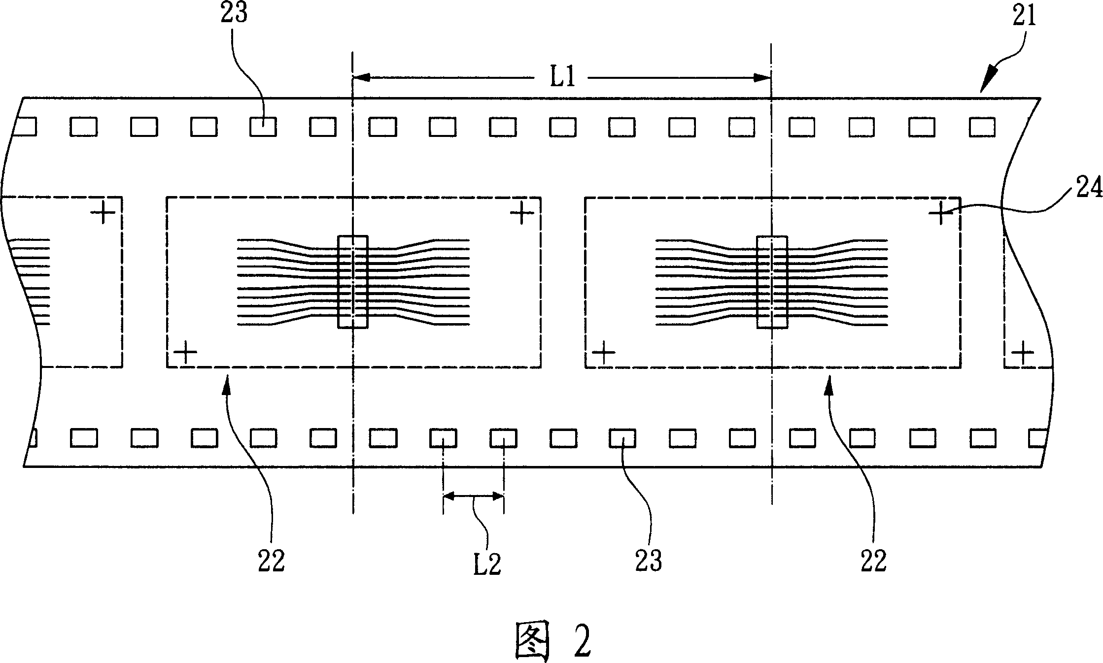
[0032] Please refer to FIG. 2 , which is a partial top view of a chip carrier tape according to a specific embodiment of the present invention. A chip carrier tape mainly includes a tape body 21 , a plurality of packaging units 22 and a plurality of counting marks 23 . The packaging units 22 have a wire structure for bonding a chip (not shown in the figure), and are suitable for TCP (Tape Carrier Package, Tape Carrier Package) or COF (Chip-On-Film, Chip-On-Film) packaging. The packaging units 22 are equidistantly arranged on the reel body 21 , and the packaging units 22 have a fixed f...


PUM


Abstract

The invention relates to a chip support coil band. Wherein, it mainly comprises a main body, dual packing units and dual counting marks; said packing units and counting marks are arranged at least one side edge of main body and outside the packing units; said packing unit has fixed first distance; the counting mark has fixed second distance; the first distance is positive integer times than the second distance, while the second distance is 0.50-3.97mm, to increase the packing unit and reduce the coil band waste.

Description

technical field [0001] The invention relates to a chip carrying tape, in particular to a chip carrying tape with side counting marks. Background technique [0002] The existing known chip carrier tape has a lead pattern, which can be used in TCP (Tape Carrier Package, tape carrier package) or COF (Chip-On-Film, chip-on-film) packaging, and has two sides on both sides of the tape. Sprocket holes for transmission. The current general specification is tape with a pitch of sprocket holes of 4.75mm. If the sprocket holes are directly used for packaging and counting, there will be a waste of reel material. [0003] Please refer to FIG. 1 , which is a partial top view of a conventional chip carrier tape. The conventional chip carrier tape mainly includes a tape body 11, and a plurality of equidistant packaging units 12 are arranged in the tape body 11, and the packaging units 12 have a first pitch P1. Each packaging unit 12 can be bonded with a chip to form a chip package (not s...

Claims


Application Information

Patent Timeline
Patent Type & Authority Applications(China)
IPC IPC(8): H01L23/00
Inventor 李明勋刘光华蔡嘉益
Owner CHIPMOS TECH INC
Why Eureka
Try Eureka