High-torque disc type permanent magnet reduction gear

A reduction gear, high-torque technology, applied in electrical components, generators/motors, etc., can solve problems such as difficulty in transmitting high torque, and achieve the effect of high magnetic energy utilization and improved magnetic energy utilization

Inactive Publication Date: 2014-07-02
HENAN POLYTECHNIC UNIV
View PDF4 Cites 12 Cited by
  • Summary
  • Abstract
  • Description
  • Claims
  • Application Information

AI Technical Summary

Problems solved by technology

When the various materials, transmission ratio and outer dimensions of the permanent magnet reduction gear are fixed, its abili

Method used


Image

  • High-torque disc type permanent magnet reduction gear
  • High-torque disc type permanent magnet reduction gear
  • High-torque disc type permanent magnet reduction gear

Examples


Embodiment Construction

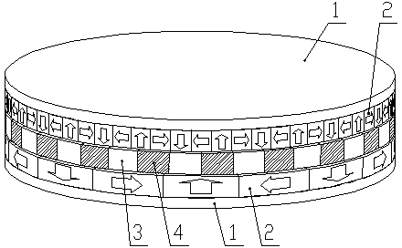
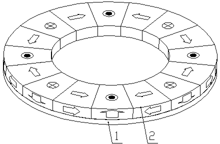
[0032] like Figure 1-Figure 16 As shown, the high-torque disc permanent magnet deceleration device of the present invention includes a coaxial and sequentially installed first permanent magnetic disc assembly, a modulation disc assembly and a second permanent magnetic disc assembly, and there is a gap between adjacent two assemblies. The gap between the first permanent disk assembly and the reticle assembly is called the primary air gap, and the gap between the reticle assembly and the second permanent disk assembly is called the secondary air gap;

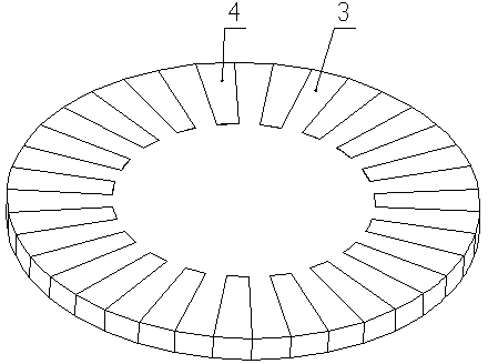
[0033] Both the first permanent magnetic disk assembly and the second permanent magnetic disk assembly include a disk-shaped yoke 1 and a permanent magnet 2, and the permanent magnets 2 are evenly distributed on the inner surface of the disk-shaped yoke 1 along the central circumferential direction of the disk-shaped yoke 1, The modulation disk assembly is located between the permanent magnet 2 of the first permanent disk assembl...


PUM


Abstract

The invention relates to a high-torque disc type permanent magnet reduction gear which comprises a first permanent magnet disc assembly, a modulating disc assembly and a second permanent magnet disc assembly. The first permanent magnet disc assembly, the modulating disc assembly and the second permanent magnet disc assembly are sequentially and coaxially installed, and gaps are reserved between two adjacent assemblies. The magnetization directions of permanent magnets on the permanent magnet disc assemblies include the axial direction, the circumferential direction and the slant direction; a plurality of magnetic poles with different magnetization directions form magnetic pole sets according to certain sequences, the magnetic pole sets on the first permanent magnet disc assembly and the second permanent magnet disc assembly are different in structure and number, and the quantitative relation of the magnetic pole sets meets the transmission ratio requirement. By means of the high-torque disc type permanent magnet reduction gear, most of magnetic energy can be gathered into an effective working area, the output torque is accordingly and substantially improved, and non-contact motion transmission of the reduction gear is achieved. The high-torque disc type permanent magnet reduction gear has two working modes; the first working mode is that the first permanent magnet disc assembly serves as a driving rotor, the modulating disc assembly is fixed to serve as a stator, and the second permanent magnet disc assembly serves as a driven rotor; the second working mode is that the first permanent magnet disc assembly serves as a driving rotor, the modulating disc assembly serves as a driven rotor, and the second permanent magnet disc assembly is fixed to serve as a stator.

Description

technical field [0001] The invention belongs to the technical field of magnetic transmission, and in particular relates to a high-torque disc-type permanent magnet reduction device. Background technique [0002] The permanent magnet reduction gear is a new type of non-contact transmission device that relies on the magnetic field coupling of permanent magnets for motion and torque transmission. It fundamentally overcomes the outstanding problems of mechanical gear friction, wear, lubrication, vibration, and noise. [0003] At present, the permanent magnet reduction gear based on the principle of magnetic field modulation already has a high torque density, so it has received extensive attention. In this reduction gear, the magnetization direction of the permanent magnet is single axial magnetization or radial magnetization. When the various materials used in the permanent magnet reduction gear, the transmission ratio and the outer dimension are fixed, its ability to transmit ...

Claims


Application Information

Patent Timeline
IPC IPC(8): H02N11/00
Inventor 张海肖磊李新郑果张小东赵若翔
Owner HENAN POLYTECHNIC UNIV
Why Eureka
Try Eureka