Method and system for DVB-T2 channel estimation

A DVB-T2, channel estimation technology, applied in multi-frequency code systems, baseband system components and other directions, can solve problems such as large hardware resource consumption and high complexity

Active Publication Date: 2014-07-02
HUNAN GOKE MICROELECTRONICS
View PDF4 Cites 15 Cited by
  • Summary
  • Abstract
  • Description
  • Claims
  • Application Information

AI Technical Summary

Problems solved by technology

This method of transforming a filter transforms a low-pass real filter into a band-pass complex filter, which shows high complexity in application and consumes a lot of hardware resources.

Method used


Image

  • Method and system for DVB-T2 channel estimation
  • Method and system for DVB-T2 channel estimation
  • Method and system for DVB-T2 channel estimation

Examples


Embodiment Construction

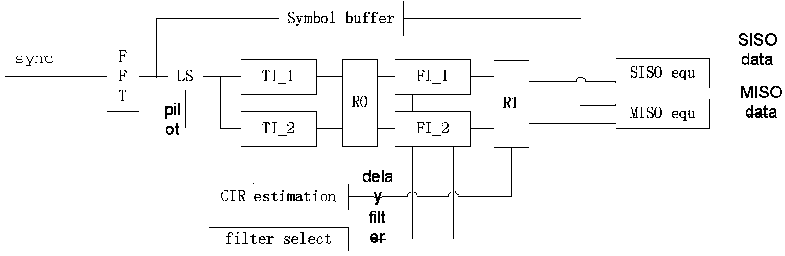
[0059] The steps of the channel estimation method of the present invention are as follows: image 3 Shown:

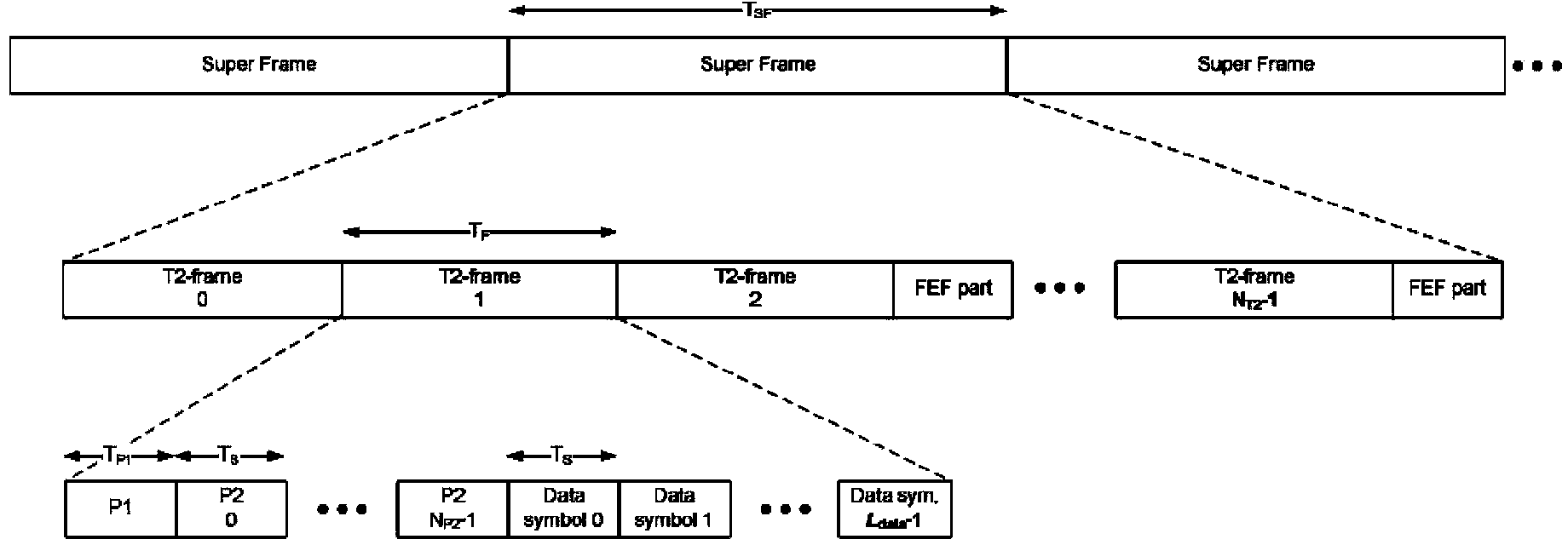
[0060] 1. After symbol synchronization, convert the time-domain data after removing the cyclic prefix into frequency-domain OFDM symbols. Store OFDM symbols until the buffer is full. The system sets 2x32K memory as OFDM cache, and the number of OFDM symbols stored corresponding to 1K, 2K, 4K, 8K, 16K, and 32K modes are 64, 32, 16, 8, 4, and 2 respectively. The system starts storing from the first P2 symbol.

[0061] 2. Extracting an OFDM symbol from the cache, and extracting the channel information of the pilot position of the symbol. Because the position and amplitude information of these pilots are known to the receiver. The obtained channel frequency domain response corresponding to the pilot position (without considering the influence of noise) can be obtained by the following formula:

[0062] H k , ...


PUM


Abstract

The invention discloses a method and system for DVB-T2 channel estimation. The method comprises the steps that filters are sequentially selected from a filter bank in a self-adaptive mode according to the relation between signal delay and frequency domain response of the signal delay and interpolation filtering in the frequency domain direction is achieved on a base band in a grouping mode, so that influence caused by noise on the system is effectively reduced and meanwhile, hardware achievement cost and power consumption are reduced. According to the method, influence caused by the noise on the DVB-T2 system is effectively reduced and the channel estimation accuracy is improved.

Description

technical field [0001] The invention relates to a DVB-T2 system, in particular to a DVB-T2 channel estimation method and system. Background technique [0002] DVB-T2 is the most advanced digital terrestrial broadcasting transmission system in the world. Compared with the first generation DVB-T, it is more effective, more robust and more flexible. The DVB-T2 system introduces the latest modulation and coding techniques. It can efficiently use the precious terrestrial spectrum for the transmission of voice, video and data services. [0003] The improvement of the performance of the new DVB-T2 system also means the improvement of the complexity of the system. Compared with DVB-T, DVB-T2 system has designed a new frame structure. Such as figure 1 shown. The frame structure of the new DVB-T2 system is a three-layer hierarchical frame structure. The basic element is a T2 frame, and several T2 frames and Future Extended Frames (FEF) form a superframe, and each T2 frame includ...

Claims


Application Information

Patent Timeline
Patent Type & Authority Applications(China)
IPC IPC(8): H04L25/02H04L27/26
Inventor 于志强
Owner HUNAN GOKE MICROELECTRONICS
Why Eureka
Try Eureka