Aerial electricity receiver

A technology of power receiving and inductors, which is applied in the direction of electrical components and naturally occurring electricity, can solve problems such as large lightning energy, burning of power storage devices, damage of power collecting devices, etc., achieves a high degree of automation, ensures safe use of electricity, The effect of avoiding harm

Inactive Publication Date: 2014-07-02
BEIJING UNION UNIVERSITY
View PDF5 Cites 1 Cited by
  • Summary
  • Abstract
  • Description
  • Claims
  • Application Information

AI Technical Summary

Problems solved by technology

However, since the automatic closing switch and the power collecting equipment such as the storage power station are connected in parallel, when lightning comes, it is very likely that the automatic closing switch has not been connected to the ground wire, and other power collecting devices have been damaged by lightning.
[0004] In addition, some scientists and inventors in the former Soviet Union have also done a lot of research and experiments on extracting electrical energy from lightning, especially using electrodes similar to lightning rods to extract electrical energy from high altitudes, but they have basically failed. The main reason is that The electric energy of the lightning was too great, and all the storage devices used in the experiment were burned

Method used


Image

  • Aerial electricity receiver
  • Aerial electricity receiver
  • Aerial electricity receiver

Examples


Embodiment 1

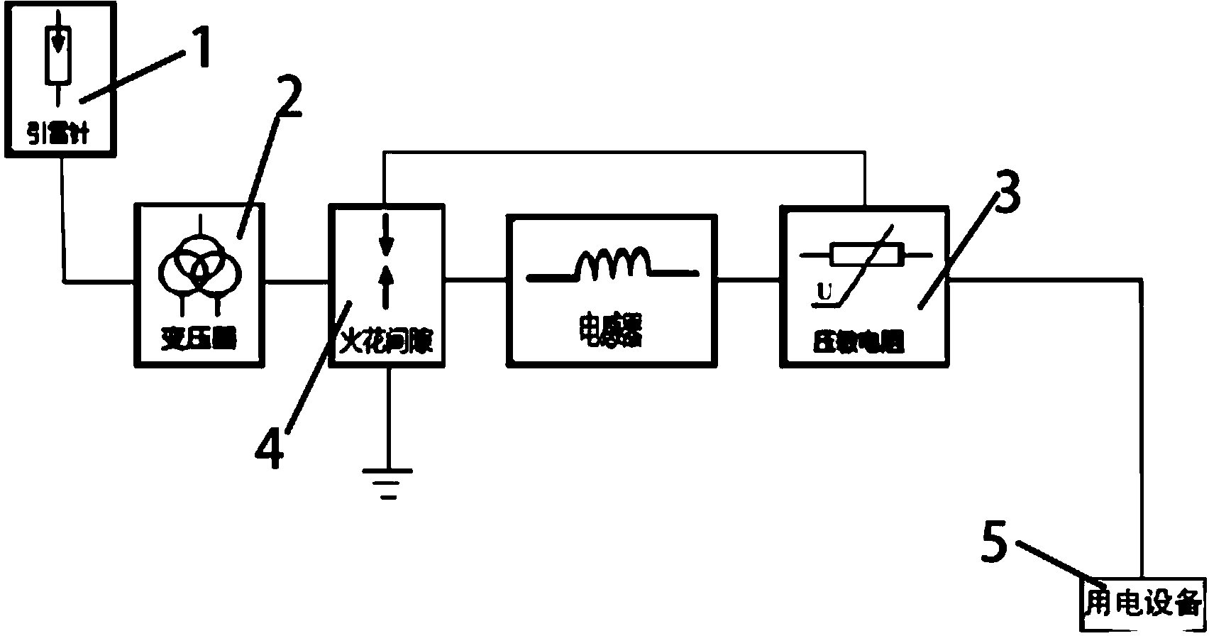
[0029] Such as figure 1 As shown, the high-altitude power receiving device includes a lightning rod 1 , a transformer, an inductor 4 , and a piezoresistor 3 , wherein one end of the transformer is connected to the lightning rod 1 , and the other end of the transformer is connected to the spark gap 4 . One end of the spark gap 4, the inductor 4 and the other end of the piezoresistor 3 are connected in series in sequence. The other end of the spark gap 4 is connected to the other end of the piezoresistor 3 . In addition, one end of the spark gap 4 is grounded, and the piezoresistor 3 is connected to the electrical equipment 5 .

Embodiment 2

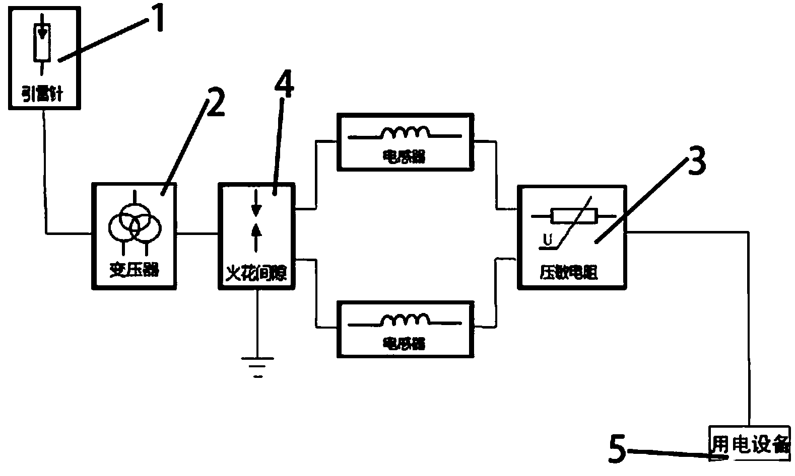
[0031] Such as figure 2 As shown, the high-altitude power receiving device includes a lightning rod 1 , a transformer 2 , two inductors, a piezoresistor 3 and a spark gap 4 . One end of the transformer 2 is connected to the lightning rod 1, and the other end is connected to the spark gap 4. One end of the spark gap 4, any inductor and one end of the varistor 3VDR1 are serially connected in series, and the other end of the spark gap 4, another inductor and the other end of the varistor 3 are also connected in series. One end of the spark gap 4 is grounded, and the piezoresistor 3 is connected to the electric device 5 .

Embodiment 3

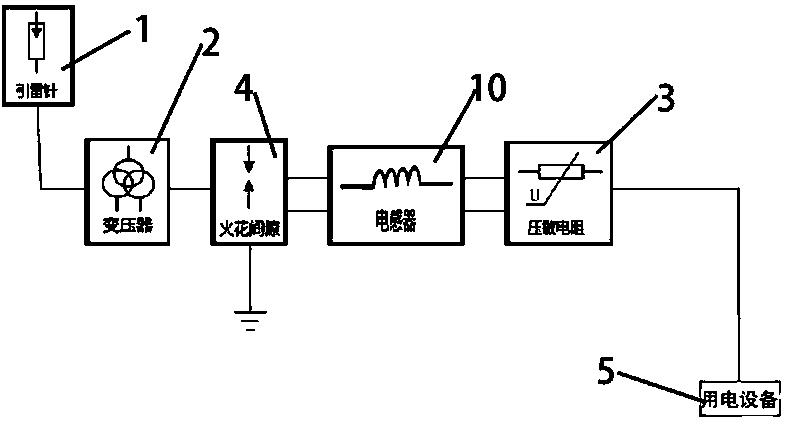
[0033] Such as image 3 As shown, the high-altitude power receiving device includes a lightning rod 1 , a transformer 2 , a common mode inductor 10 , a piezoresistor 3 and a spark gap 4 . One end of the transformer 2 is connected to the lightning rod 1, and the other end is connected to the spark gap 4. One end of the spark gap 4, one winding of the common mode inductor 10, and one end of the varistor 3 are connected in series in sequence, and the other end of the spark gap 4, another winding of the common mode inductor 10, and the other end of the varistor 3 are also connected in sequence in series. One end of the spark gap 4 is grounded, and the piezoresistor 3 is connected to the electric device 5 .

[0034]According to the principle of the high-altitude power receiving device in Embodiments 1-3 of the present invention: After receiving the cloud layer charge led by the lightning rod 1, the transformer 2 will first transform the voltage between the clouds, and then send i...


PUM


Abstract

The invention relates to an aerial electricity receiver comprising a lightning rod (1), a transformer (2), a piezoresistor (3) and a spark gap (4). The lightning rod (1) is connected to the transformer (2). The transformer (2), the spark gap (4) and the piezoresistor (3) are serially connected in sequence. A plurality of schemes providing the aerial electricity receiver are provided; the aerial electricity receiver is capable of automatically collecting cloud charge and converting into available electricity; if lightning of excessively high voltage is collected, the aerial electricity receiver automatically disconnects with an electric device and guides the lightning to the ground, and the excessively high voltage endangering people's life and property safety is prevented.

Description

technical field [0001] The invention belongs to the technical field of lightning reception, and in particular relates to a high-altitude electric energy receiving device. Background technique [0002] There is often huge electric energy in the sky, for example, in the clouds, thunder and lightning are often formed, and sometimes it brings disasters to human beings. If these electric energies can be collected, it will not only reduce disasters and turn waste into wealth, but also reduce or even eliminate the use of polluting energy, which is beneficial to environmental protection. Kites have been invented in the past to harvest electricity from clouds. But the kite can only fly in the direction of the wind, and it is difficult to control when the wind is too strong. Therefore, the idea of ​​using kites to collect high-altitude electrical energy has basically not been put into practice in the process of practical application, it is just an idea. [0003] The Chinese inventi...

Claims


Application Information

Patent Timeline
Patent Type & Authority Applications(China)
IPC IPC(8): H05F7/00
Inventor 赵杰民
Owner BEIJING UNION UNIVERSITY
Why Eureka
Try Eureka