

Vane compressor
A compressor and blade-type technology, applied in the field of blade-type compressors, can solve problems such as the small distance between rotors, and achieve the effects of avoiding contact, reducing mechanical loss, and suppressing sliding resistance
- Summary
- Abstract
- Description
- Claims
- Application Information
AI Technical Summary
Problems solved by technology
Method used
Image

Examples
Embodiment approach 1
[0037] (Structure of vane compressor 200)
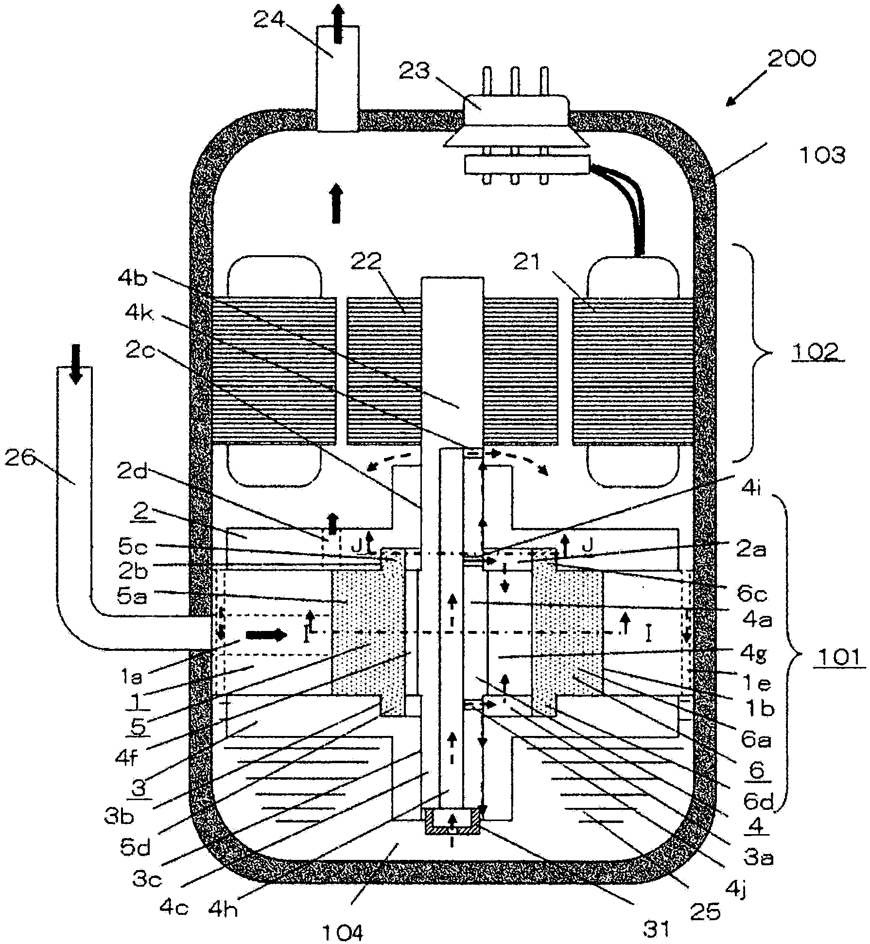
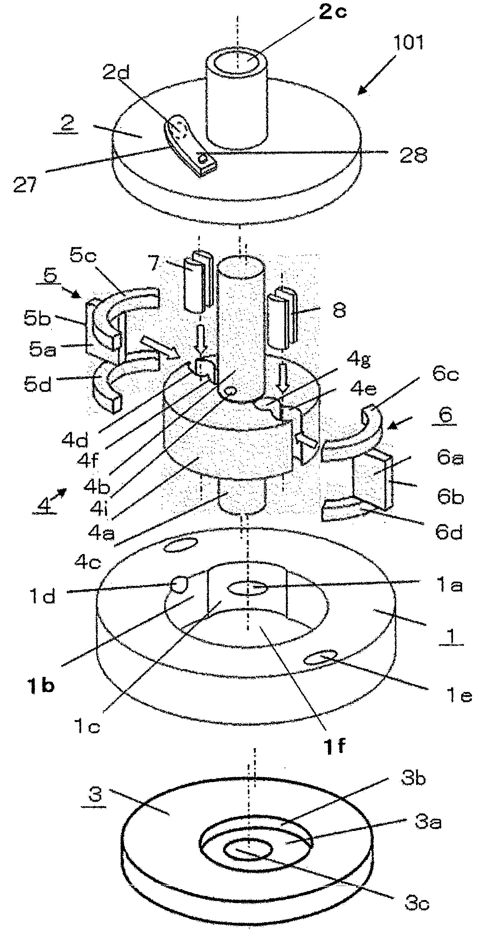
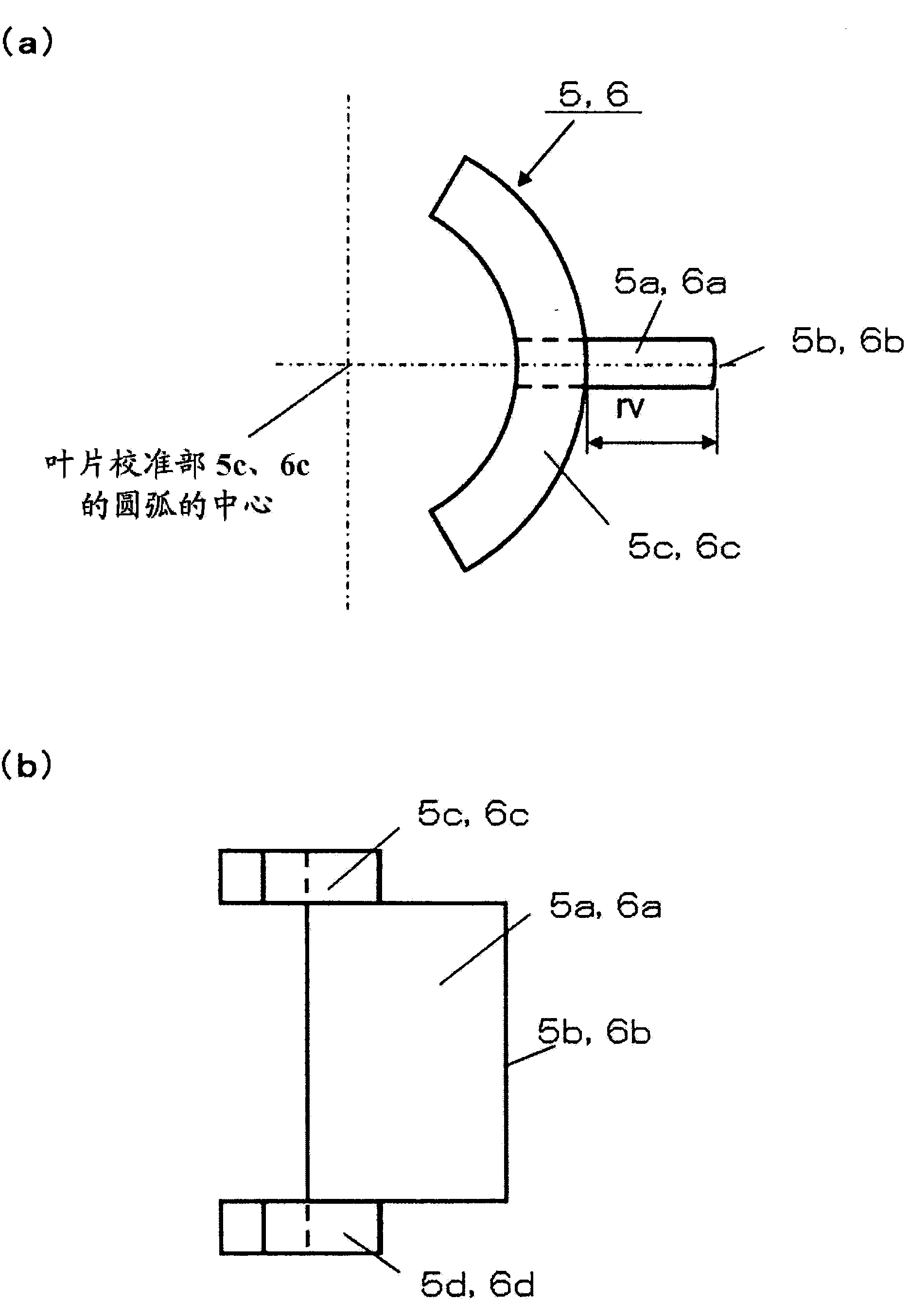
[0038] figure 1 It is a longitudinal sectional view of vane compressor 200 according to Embodiment 1 of the present invention, figure 2 It is an exploded perspective view of the compression unit 101 of the vane compressor 200 . in addition, image 3 It is a plan view and a front view of the first vane 5 and the second vane 6 of the vane compressor 200, Figure 4 It is a perspective view of the bushes 7 and 8 of the vane compressor 200 . Among them, in figure 1 In , arrows indicated by solid lines indicate the flow of gas (refrigerant), and arrows indicated by broken lines indicate the flow of refrigerating machine oil 25 . Below, refer to Figure 1 to Figure 4 The structure of the vane compressor 200 will be described.
[0039] The vane compressor 200 of this embodiment is composed of the following components: an airtight container 103 forming an external shape; a compression unit 101 accommodated in the airtight container 10...
Embodiment approach 2
[0093] Regarding the vane compressor 200 of this embodiment, the difference from the vane compressor 200 of Embodiment 1 will be mainly described.
[0094] (Structure around blade parts 5a, 6a)
[0095] Figure 12 It is a cross-sectional view of key parts around the vane portion 5a of the first vane 5 when the angle 7h of the vane compressor 200 according to Embodiment 2 of the present invention is maximized.
[0096] Figure 12 In the state shown, the angle 7h formed by the straight line 7f connecting the center of the rotor portion 4a and the center 7a of the bushing 7 and the straight line 7g connecting the center of the cylinder inner peripheral surface 1b and the center 7a of the bushing is at the angle 7h of the rotor shaft 4. Become the largest state in one rotation. In this state, the ends of the notched surfaces 7c and 7d are formed closest to the inner peripheral surface of the bush holding portion 4d, but do not slide. Therefore, even if the rotation angle of th...
Embodiment approach 3
[0101] Regarding the vane compressor 200 of this embodiment, the difference from the vane compressor 200 of Embodiment 1 will be mainly described.
[0102] (Structure around blade parts 5a, 6a)
[0103] Figure 13 It is a cross-sectional view of key parts around the vane portion 5a of the first vane 5 at an "angle of 0°" of the vane compressor 200 according to Embodiment 3 of the present invention.
[0104] Such as Figure 13 As shown, the notched surfaces 7c and 7d of the bushing 7 are formed as arc-shaped curved surfaces convex upward. Therefore, the end portions of the notched surfaces 7c and 7d are rounded compared to the case of Embodiment 1, so that even when sliding relative to the inner peripheral surface of the bush holding part 4d, the stress on the bush holding part 4d can be reduced. possibility of damage.
[0105] In addition, the structure of the bush 8 is the same as that of the bush 7 described above.
[0106] (Effect of Embodiment 3)
[0107] According t...
PUM
 Abstract
Description
Claims
Application Information