Supercharge Your Innovation With Domain-Expert AI Agents!

Sealing device

A sealing device and sealing component technology, applied in sealing, engine sealing, packaging, etc., can solve problems such as increased sliding resistance, increased torque, and increased sliding area between the sealing component 810 and the shaft 600, so as to reduce sliding wear and achieve sliding Increased resistance and long-term sealing effect

Inactive Publication Date: 2020-05-26
NOK CORP
View PDF7 Cites 0 Cited by
  • Summary
  • Abstract
  • Description
  • Claims
  • Application Information

AI Technical Summary

Problems solved by technology

[0007] As described above, in the case of the sealing device 800 of the conventional example, by providing the leaf spring 820, the sealing performance is maintained for a long period of time, but the sliding area between the sealing member 810 and the shaft 600 increases with time.
As a result, sliding resistance increases and torque increases

Method used


Image

  • Sealing device
  • Sealing device
  • Sealing device

Examples


Embodiment Construction

[0037] Hereinafter, with reference to the accompanying drawings, an exemplary detailed description will be given of the manner for implementing the present invention based on embodiments. Among them, the size, material, shape, and relative arrangement of the structural components described in this embodiment, unless otherwise stated, do not mean that the scope of the present invention is limited to these.

[0038] (Example)

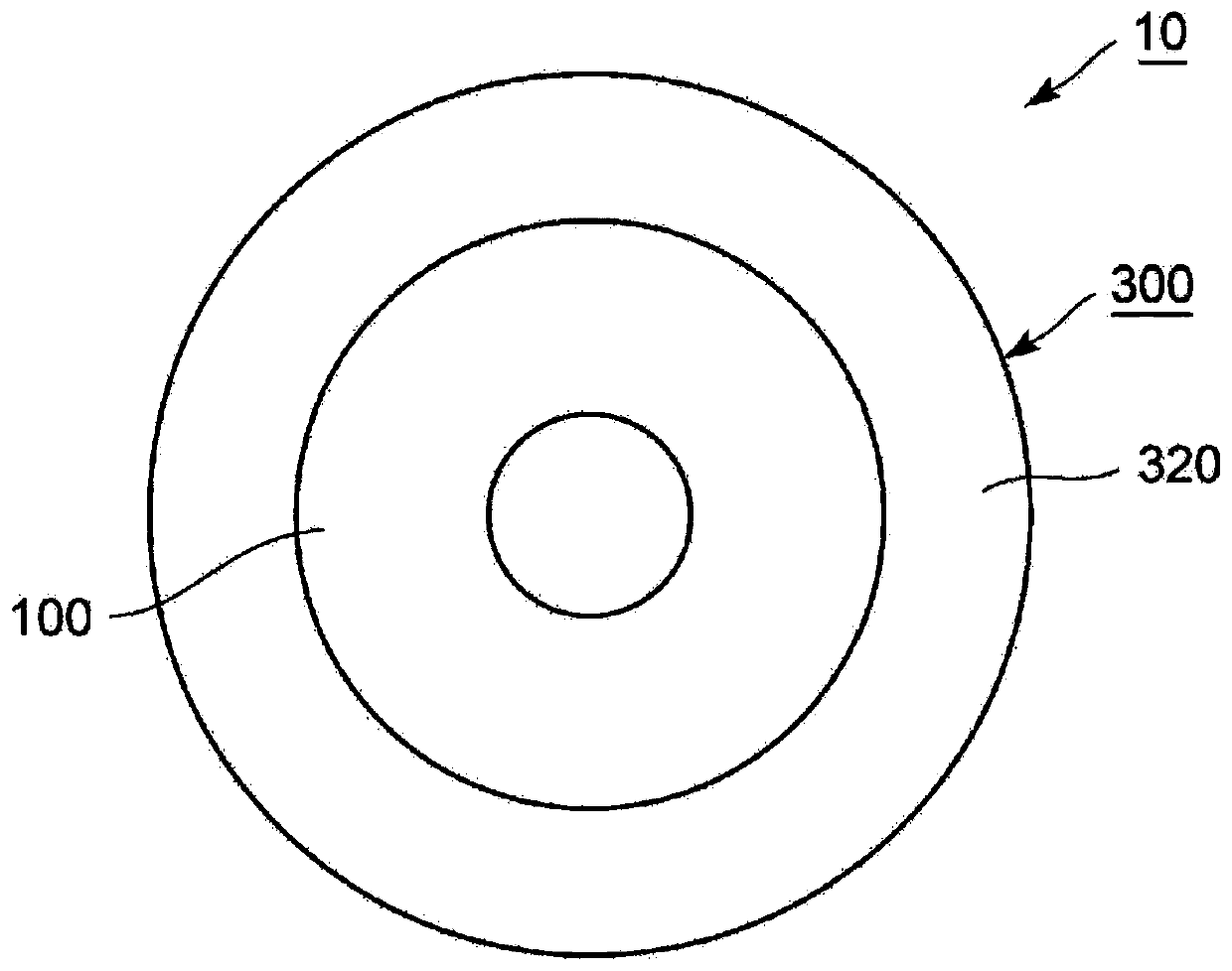
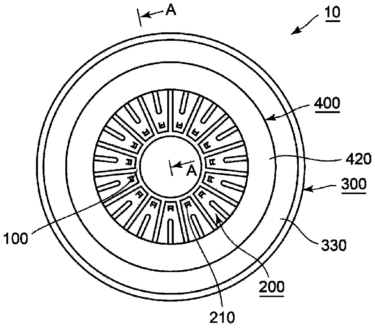
[0039] Reference Figure 1 ~ Figure 7 , The sealing device of the embodiment of the present invention is explained. The sealing device 10 of this embodiment is used, for example, in an exhaust gas system such as EGR to seal the annular gap between the relatively rotating shaft 600 and the housing 700. Therefore, the sealing device 10 is used in a high-temperature environment. Here, in the following description, the "sealing target fluid side" refers to the side where the sealing target fluid is sealed. That is, even if the fluid to be sealed is not actually...


PUM


Abstract

Provided is a sealing device configured so that the sealing properties can be maintained for a long period of time and an increase in sliding resistance can be suppressed. The sealing device is characterized in that a plurality of protrusions 210 are provided at circumferential intervals on a plate spring 200. The protrusions 210 is configured so that, as a shaft 600 is inserted into a shaft holein a housing 700, the protrusions 210 bite into a seal member 100 in a process in which the radially inner side of the seal member 100 is curved and deformed toward the sealed fluid side, and the radially inner side of the plate spring 200 is curved and deformed along the seal member 100.

Description

Technical field [0001] The present invention relates to a sealing device including a sealing member made of polytetrafluoroethylene. Background technique [0002] Against the background of compliance with environmental regulations, a sealing device used in an exhaust gas system such as EGR to seal an annular gap between a relatively rotating shaft and a housing is required to further stabilize the sealing performance. Therefore, the applicant proposes a technology related to a sealing device as follows, that is, the sealing device uses a sealing member made of polytetrafluoroethylene (PTFE) that is excellent in heat resistance and less sliding wear, and due to the performance of the sealing member As a countermeasure against permanent strain caused by the creep phenomenon at this time, a leaf spring is used (see Patent Document 1). Reference Figure 8 ~ Figure 10 , The sealing device of the conventional example will be described. [0003] Figure 8 It is a schematic cross-sectiona...

Claims


Application Information

Patent Timeline
Patent Type & Authority Applications(China)
IPC IPC(8): F16J15/3212F16J15/3204
CPCF16J15/3212F16J15/3268Y10S277/946F16J15/3204
Inventor 江口信行
Owner NOK CORP
Features
  • R&D
  • Intellectual Property
  • Life Sciences
  • Materials
  • Tech Scout
  • Unparalleled Data Quality
  • Higher Quality Content
  • 60% Fewer Hallucinations
Learn More