
Acoustic deashing and dedusting device

A sonic cleaning and dust removal technology, which is applied in electrode cleaning, chemical instruments and methods, and separation of dispersed particles, can solve the problems that dust cannot be completely removed, operating costs increase, and dust removal efficiency is low, so as to save manpower and reduce Maintenance cost, good cleaning effect

Inactive Publication Date: 2014-07-09
ZHEJIANG JITIAN ENVIRONMENTAL PROTECTION TECH
View PDF8 Cites 8 Cited by
  • Summary
  • Abstract
  • Description
  • Claims
  • Application Information

AI Technical Summary

Problems solved by technology

[0006] The dust removal technology currently used in the existing environmental protection dust removal equipment still stays on the traditional mechanical vibration or pulse jet dust removal. When the dust accumulates on the plate or filter material, the dust cannot be removed completely, causing resistance Rising, resulting in higher operating costs and low dust removal efficiency

Method used


Image

  • Acoustic deashing and dedusting device
  • Acoustic deashing and dedusting device

Examples


Embodiment 1

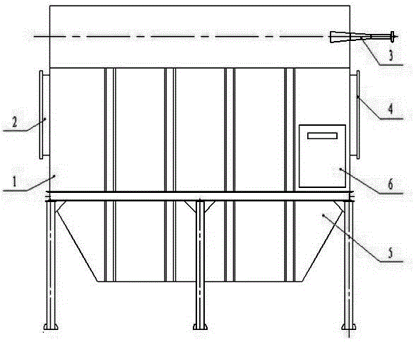
[0025] Embodiment 1: A bag filter for sonic cleaning, comprising: a box body 1 for support and protection; an air inlet 2 arranged on one side of the box body 1 and an air outlet 4 on the opposite side, respectively for Pass in dusty gas and discharge clean gas. The air inlet 2 controls the filtering wind speed below 1.0m / min; the air outlet 4 is connected to a negative pressure fan to maintain a negative pressure environment in the box body 1. The ash hopper 5 is arranged under the box body 1 to receive the dust collected by the dust collector, and a column is also arranged under the ash hopper 5 to play a supporting role.

[0026] It also includes an acoustic wave generator 3 arranged on the box body 1 for cleaning the dust deposited on the surface of the filter bag inside the box body 1 . Described acoustic wave generator 3 is arranged on the side wall of casing 1, and the frequency setting of acoustic wave generator and the size of casing 1 need to satisfy following condi...

Embodiment 2

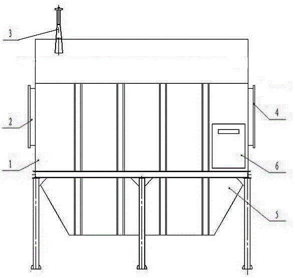
[0033] Embodiment 2: a kind of electric precipitator of sonic cleaning, as figure 2 As shown, it includes: a box body 1 for support and protection; an air inlet 2 arranged on one side of the box body 1 and an air outlet 4 on the opposite side, which are respectively used for introducing dusty gas and discharging clean gas. The air inlet 2 controls the filtering wind speed below 1.0m / min; the air outlet 4 is connected to a negative pressure fan to maintain a negative pressure environment in the box body 1. The ash hopper 5 is arranged under the box body 1 to receive the dust collected by the dust collector, and a column is also arranged under the ash hopper 5 to play a supporting role.

[0034] It also includes an acoustic wave generator 3 arranged on the box body 1, which is used to clean the dust deposited on the surface of the inner pole plate and polar line of the box body 1. The sound wave generator 3 is arranged on the top of the box body 1, and the frequency setting of...


PUM


Abstract

The invention relates to a deduster and discloses an acoustic deashing and dedusting device. The acoustic deashing and dedusting device comprises a box, an air inlet, an air outlet, an ash bucket arranged below the box and a negative pressure draught fan connected with the air outlet. The acoustic deashing and dedusting device is characterized by further comprising an acoustic transmitter. According to the invention, acoustic deashing technology is employed, and dust accumulated on pole plates and pole wires of an electric precipitator or on the filter material of a bag filter can be effectively removed. The acoustic deashing and dedusting device can remove dust accumulated on the surface of the pole plates or filter material and has the advantages of a good deashing effect, a simple structure, high purifying efficiency, long service life, safe and reliable operation and a high degree of automation.

Description

[0001] technical field [0002] The invention relates to a dust remover, in particular to a dust remover which utilizes sound waves to remove dust. Background technique [0003] With the development of industrial production and the improvement of people's awareness of environmental protection, coupled with various smog phenomena and the national environmental standards for dust concentration emission requirements, various dust removal technologies have been developed, and various dust collectors have come into being. pregnancy. [0004] So far, electrostatic precipitators and bag (cartridge) precipitators are the most widely used dust collectors. Whether it is an electrostatic precipitator or a bag filter, there is a common problem, that is, it is difficult to clean the dust. Electrostatic dust removal relies on mechanical rapping of the plate of the dust collector to remove dust. Long-term mechanical rapping will inevitably cause damage to the plate or pole line and the me...

Claims


Application Information

Patent Timeline
IPC IPC(8): B03C3/74B01D46/04
Inventor 胡瑜凤琚国锋
Owner ZHEJIANG JITIAN ENVIRONMENTAL PROTECTION TECH
Learn More