
A cone machine

A technology of tapered pipe machine and machine base, which is applied in the field of tapered pipe machine, which can solve the problems of high machine noise, high mold matching precision, inconvenient axial adjustment, etc., and achieve convenient position adjustment, improved service life, and good taper Effect

Inactive Publication Date: 2015-09-23
NINGBO LEBO INTELLIGENT MACHINERY
View PDF7 Cites 0 Cited by
  • Summary
  • Abstract
  • Description
  • Claims
  • Application Information

AI Technical Summary

Problems solved by technology

[0004] The mold block and its hammer head block in the above-mentioned tapered tube machine slide in the mold cavity of the main shaft along the radial direction of the main shaft, which is inconvenient to adjust in the axial direction; Inconvenient; there is no noise reduction measure, and the machine is noisy, so it is necessary to improve

Method used


Image

  • A cone machine
  • A cone machine
  • A cone machine

Examples


Embodiment Construction

[0028] The following descriptions are only preferred embodiments of the present invention, and therefore do not limit the protection scope of the present invention.

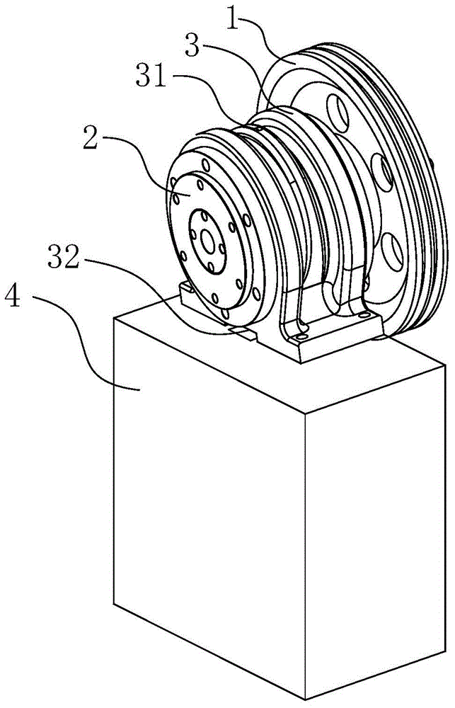
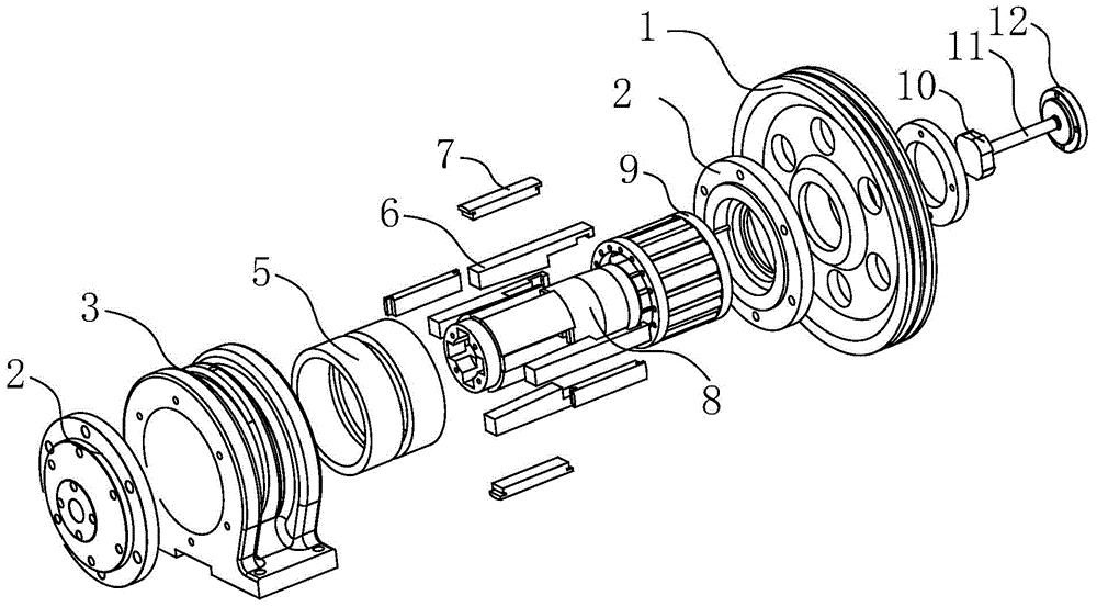
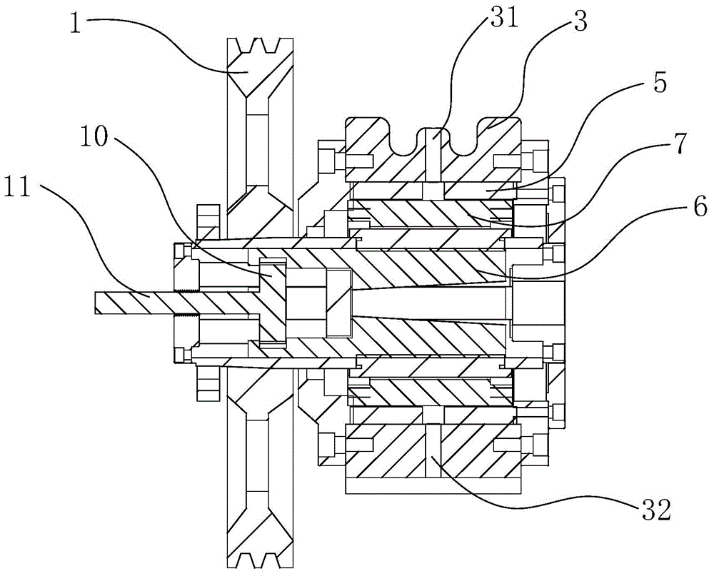
[0029] Examples, see e.g. Figure 1 to Figure 3 As shown, the present invention relates to a tapered tube machine, comprising a machine base 3, a main shaft 8 and a roller 9 installed in the machine base 3, the machine base 3 is installed on an oil tank 4, and lubricating oil is arranged in the oil tank 4, and the machine base 3 Placed vertically with the fuel tank 4 on the ground, an oil inlet 31 is arranged above the machine base 3, a pipeline connected to the fuel tank 4 is installed on the oil inlet 31, and an oil outlet is arranged below the machine base 3 32, the oil outlet 32 ​​is connected to the oil tank 4.

[0030] Such as Figure 1 to Figure 7 As shown, a main shaft 8 is installed in the machine base 3, the main shaft 8 includes a mold part 82 and a power part 81, the mold part 82 is installed in the...


PUM


Abstract

The invention discloses a tapered pipe machine. The tapered pipe machine comprises an engine base, a main shaft and an idler wheel, wherein the main shaft comprises a mould part and a power part; a mould cavity is formed in the radial direction of the mould part, and is internally provided with a mould plate; the main shaft is sleeved with the idler wheel; the mould plate comprises an impacting plate and a striking plate; the impacting plate is mounted in the mould cavity and can slide along the radial direction of the main shaft; the mould part is provided with a mould hole; the power part is provided with a positioning hole; the mould hole and the positioning hole are separated by a separation plate; a plurality of adjusting holes are formed in the axial direction of the main shaft; the striking plate is provided with a positioning part and is arranged inside the mould hole along the adjusting holes and the positioning part penetrates through the separation plate to enter the positioning hole; the positioning hole is internally provided with a positioning mechanism; the positioning mechanism can drive the striking plate to move along the axial direction of the main shaft; an oil inlet is formed in one side of the engine base and an oil outlet is formed in the other side of the engine base; lubricating oil can flow in a space between the main shaft and the idler wheel. The tapered pipe machine has the advantages of convenience for adjustment, simple structure and low noises.

Description

technical field [0001] The invention belongs to the technical field of metal extrusion, and relates to a tapered pipe machine. Background technique [0002] The tapered pipe machine is a machine tool for forging and elongating the pipe fittings into a cylindrical or conical shape through cold forging. With the cooperation of reasonable molds, it can process tapered workpieces with relatively ideal strength and smoothness. [0003] Chinese patent CN102699083A discloses a steel pipe taper machine, which includes a machine base, a housing on the machine base, and a main shaft driven by a motor. A mold and a hammer are installed in the mold cavity of the main shaft. There is a roller group, the hammer head includes a plurality of hammer head blocks, and the mold is composed of at least three mold blocks. The joint part of each mold block is triangular, and a part of the conical surface groove is set on the top side of the joint part. There is a gap between the two side walls of...

Claims


Application Information

Patent Timeline
IPC IPC(8): B21C37/18
Inventor 王贤勇郑建强桂志宏
Owner NINGBO LEBO INTELLIGENT MACHINERY
Learn More