Eureka AIR delivers breakthrough ideas for toughest innovation challenges, trusted by R&D personnel around the world.

Automatic winding roll

An automatic reeling and reeling technology, applied in the field of reels, can solve the problems of unfavorable manufacturing cost and reliability, complex brake and release structures, and complex parts structures, etc., and achieves high commercial value, simple structure, and simple assembly. Effect

Active Publication Date: 2014-07-09
JIASHAN FUJITECH PLASTIC
View PDF8 Cites 2 Cited by
  • Summary
  • Abstract
  • Description
  • Claims
  • Application Information

AI Technical Summary

Problems solved by technology

[0004] The technical problem to be solved in the present invention is: the existing automatic reel, its brake, release structure is more complicated, adopts many parts, and the part structure is more complicated, and it is that the brake, release structure is all more complicated, adopts zero There are many parts and the structure of the parts is complex, which has a negative impact on the material cost, manufacturing cost and reliability of the reel

Method used


Image

  • Automatic winding roll
  • Automatic winding roll
  • Automatic winding roll

Examples


Embodiment Construction

[0024] The present invention will be further described below in conjunction with specific examples.

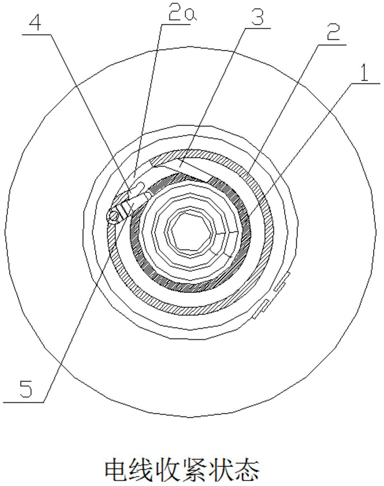
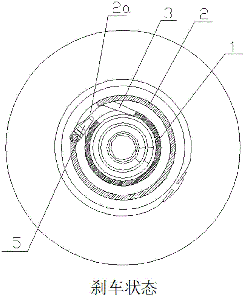
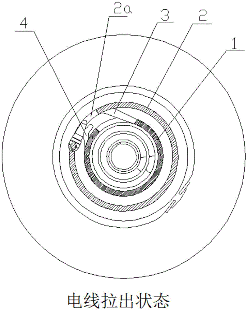
[0025] see Figure 1-3 , a kind of automatic reel, the reel wound on the automatic reel is subjected to the external force of automatic roll-up under the action of the elastic recovery mechanism, and the inner ring groove 1, the outer ring groove 2. The clamping rod 5, the protruding head of the clamping rod 5 is stuck in the inner and outer ring grooves 1 and 2 and slides along it; The trajectory direction is outward, otherwise it is inward; the inner ring groove 1 is smoothly connected with the outer ring groove 2 through the connecting groove 3, and there is a step I at the side of the connecting groove 3 adjacent to the inner ring groove, and the connecting groove 3 Located at the lower level of the step I; the connecting position of the outer ring groove 2 and the connecting groove is outward, passing through the first section 2a of the outer ring groove, and a step II i...


PUM


Abstract

The invention relates to an automatic winding roll. A coil winding round the automatic winding roll is under the action of external force generated by automatic winding under the action of an elastic resetting mechanism. The automatic winding roll is characterized in that an inner ring groove, an outer ring groove and a clamping rod are arranged on the winding roll, and the raised head of the clamping rod is clamped in the inner and outer ring grooves and slides along the inner and outer ring grooves; the inner ring groove is in smooth communication with the outer ring groove through a joint groove, a step I is formed at a position adjacent to the inner ring groove beside the joint groove, and the joint groove is positioned at the lower stage of the step I; the joint position of the outer ring groove and the joint groove face outwards and passes through the head segment of the outer ring groove, a step II is formed at the tail end of the head segment of the outer ring groove, the head segment of the outer ring groove is positioned at the upper stage of the step II, and the secondary segment of the outer ring groove is positioned at the lower stage of the step II; a herringbone clamping groove is formed between the start position of the secondary segment of the outer ring groove and the inner and outer ring grooves, a step III is formed at the inlet of the clamping groove, the clamping groove is positioned at the lower stage of the step III, the outlet of the clamping groove is communicated with the inner ring groove, a step IV is formed between the outlet of the clamping groove and the inner ring groove, and the inner ring groove is positioned at the lower stage of the step IV.

Description

technical field [0001] The invention relates to an automatic wire reel, which belongs to the technical field of wire reels. Background technique [0002] The reel is used to retract the power cord. When the length of the power cord is long, it is convenient to organize the power cord. According to the required length of the power cord, pull the power cord out of the reel and adjust it to "Brake" fixation after proper length. [0003] The automatic reel in the prior art, for example: Patent No. 201120121385.9, a Chinese utility model patent titled "Reel Brake Release Lever and Reel Brake Release Device", which discloses the use of the brake release lever ( Including the button part, the elastic part and the shaft hole) to realize the brake release; the application number is 201110270914.6, and the Chinese invention patent application named "brake structure of the reel" discloses the use of ratchet pawl brake components and friction brakes Components to realize the brake str...

Claims


Application Information

Patent Timeline
Patent Type & Authority Applications(China)
IPC IPC(8): B65H75/44
Inventor 黄福顺
Owner JIASHAN FUJITECH PLASTIC
Why Eureka
Eureka Blog
Learn More