Sponge iron elevator of powder metallurgy reduced iron powder industry and system

A technology of reducing iron powder and powder metallurgy, which is applied in the direction of furnaces, furnace types, fluidized bed furnaces, etc., can solve the problems of increasing magnetic separation load, large area occupied by system equipment, and large equipment occupied area, so as to facilitate maintenance Effects of maintenance, space saving, and effective use of space

Inactive Publication Date: 2014-07-09
LAIWU TAIDONG POWDER TECH
View PDF8 Cites 2 Cited by
  • Summary
  • Abstract
  • Description
  • Claims
  • Application Information

AI Technical Summary

Problems solved by technology

[0005] ⑴This process arrangement determines that the extruder is arranged below the ground, which is not conducive to the inspection and maintenance of the equipment;
[0006] ⑵The crushing machine is arranged underground, and the crushed sponge iron block must be sent to the coarse crushing machine above the ground through the inclined belt. Due to the limitation of the lifting angle of the belt conveyor, the distance between the crushing machine and the rough crushing machine is generally 5 meters Above, the system equipment occupies a large area; if the coarse crusher is installed underground, a belt transmission device must be installed between the crusher and the extruder, which also has the problem of large equipment occupation;
[0007] (3) The extruder is arranged underground, and the crushed sponge iron blocks are easy to push in together, but the falling reducing agent and desulfurizing agent are also easy to push in together, which not only increases the workload of coarse crushing, but also increases the load of subsequent magnetic separation, seriously It will reduce the magnetic separation effect and affect the quality of primary powder;
[0008] ⑷The extruder is arranged underground, which is not conducive to the combined use of sponge iron of different grades before coarse crushing
[0009] At present, there is no report on the sponge iron hoist device

Method used


Image

  • Sponge iron elevator of powder metallurgy reduced iron powder industry and system
  • Sponge iron elevator of powder metallurgy reduced iron powder industry and system
  • Sponge iron elevator of powder metallurgy reduced iron powder industry and system

Examples


Embodiment Construction

[0044] The present invention will be further described below in conjunction with the accompanying drawings and embodiments.

[0045] refer to figure 1 , figure 2 , Figure 3a , Figure 3b , Figure 4 , Figure 5 , Figure 6a , Figure 6b , Figure 6c , Figure 7 Make the invention.

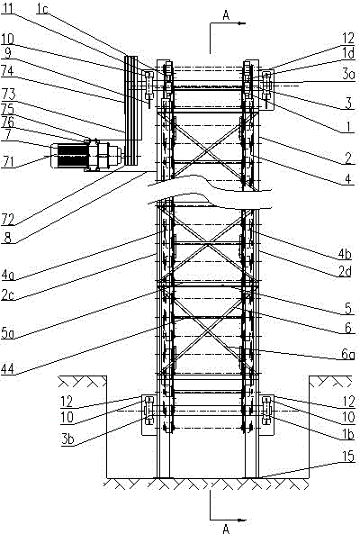
[0046] The sponge iron hoist includes a hoist reversing sprocket 1 and a hoist frame 2, the hoist reversing sprocket 1 is composed of an upper reversing sprocket 1a and a lower reversing sprocket 1b, the upper reversing sprocket 1a, The left sprocket 1c and the right sprocket 1d are respectively arranged on the lower reversing sprocket 1b and are respectively fixed on the sprocket shaft 3; It is connected by the left long-pitch roller chain 4a and the right long-pitch roller chain 4b.

[0047] The hoist frame 2 is composed of an upper frame 2a and a lower frame 2b. Both the upper frame 2a and the lower frame 2b are composed of a left frame 2c and a right frame 2d. The upper frame 2a is...


PUM


Abstract

The invention discloses a sponge iron elevator of powder metallurgy reduced iron powder industry. The elevator comprises a pair of frames which are arranged inclinedly to the horizontal plane and are parallel to each other; each frame comprises two symmetrical parts, an upper part and a lower part; the two symmetrical parts of each frame are connected by connecting straight rods and inclined support assemblies which are arranged with intervals; the pair of frames are also connected by connecting straight rods and inclined support assemblies which are arranged with intervals; a sprocket wheel is mounted respectively at the upper end and the lower end of each frame; the upper sprocket wheel and the lower sprocket wheel of each frame are connected by a chain; the chains of the two frames are connected by a support bar; an elevating handle is mounted on an inner side chain plate of each chain; the upper sprocket wheel is connected with a drive device. The invention also discloses a sponge iron elevating system of powder metallurgy reduced iron powder industry. The elevator of the invention is simple in structure, stable in operation, and convenient for maintenance, realizes effective space utilization, realizes stereoscopic arrangement of system equipment, and realizes effectively cooperative use of sponge iron with different grades.

Description

[0001] technical field [0002] The invention relates to a hoist and a system, in particular to a sponge iron hoist and a system in the powder metallurgy reduced iron powder industry. Background technique [0003] At present, in the production of powder metallurgy, with the continuous improvement of mechanization and automation and the gradual expansion of production scale, more and more enterprises use SiC tanks as reducing refractory tanks and adopt ring loading method to produce sponge iron. . The raw materials, reducing agent and desulfurizing agent processed in the material preparation process are loaded into the reduction refractory tank by the ring packing method, and are once reduced in the tunnel kiln to produce sponge iron. reduction. [0004] Sponge iron is usually stacked next to the feed pit of the extruder before crushing, and manually pushed into the feed pit for crushing operation. This process layout method is piled on the ground during production, which i...

Claims


Application Information

Patent Timeline
Patent Type & Authority Applications(China)
IPC IPC(8): C21B13/00B22F9/04
Inventor 吕学进蔺存栋赵星王道伟曹乃红郭强刘辉王凯亓国瑞
Owner LAIWU TAIDONG POWDER TECH
Why Eureka
Try Eureka