Simulating system used for shield tunnel synchronous grouting test and test method thereof

A technology of synchronous grouting and simulation system, applied in the field of underground construction engineering

Inactive Publication Date: 2014-07-09
TONGJI UNIV +1
View PDF5 Cites 52 Cited by
  • Summary
  • Abstract
  • Description
  • Claims
  • Application Information

AI Technical Summary

Problems solved by technology

[0006] In order to overcome the defect that the existing grouting method cannot perform synchronous grouting simulation tests under differe

Method used


Image

  • Simulating system used for shield tunnel synchronous grouting test and test method thereof
  • Simulating system used for shield tunnel synchronous grouting test and test method thereof
  • Simulating system used for shield tunnel synchronous grouting test and test method thereof

Examples


Embodiment

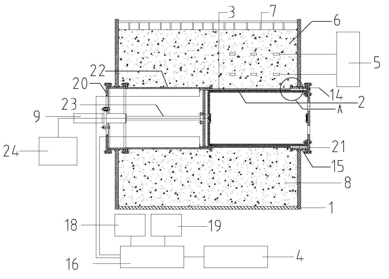
[0083] figure 1 It is a structural schematic diagram of the present invention. Wherein, the tube piece 2 is a transparent organic glass cylindrical member, and the right opening end is fixed to the right end cap 21 and arranged coaxially. The steel guide barrel 22 is a steel circular tubular member with openings at both ends, and its axis is horizontally arranged in the soil box 1. The bolts are fixed and welded to the opening of the left soil box. The opening end of the right side is tightly sleeved on the outside of the steel simulated shield shell 3, and the simulated shield shell 3 is tightly sleeved on the outside of the simulated segment 2. The simulated shield shell 3 The right end is overlapped with the upper connecting rod 14 of the right end cover and the lower connecting rod 15 of the right end cover, the right end of the simulated segment 2 is fixed with the bolts of the right end cover, and the upper connecting rod 14 of the right end cover and the lower connect...


PUM


Abstract

Disclosed is a simulating system used for a shield tunnel synchronous grouting test. The system includes model soil, model grout and a synchronous grouting simulating test platform. The model grout is injected into the model soil through the synchronous grouting simulating test platform. The synchronous grouting simulating test platform includes a soil box, a data acquisition system, a loading system, a shield propulsion control system, a simulating shield tunneling machine, pressure sensors and a grouting system. The simulating shield tunneling machine and the model soil are arranged in the soil box. The invention also discloses a test method which uses the simulating system used for the shield tunnel synchronous grouting test. The method includes: 1) preparing the model soil; 2) preparing the model grout; 3) constructing a shield-soil-grout similar system to carry out synchronous grouting tests of different grouting positions, different grouting holes and different grouting quantity allocation proportions.

Description

technical field [0001] The invention belongs to the technical field of underground construction engineering, and relates to a simulation system for synchronous grouting test of a shield tunnel and a test method thereof. Background technique [0002] During the construction of the shield tunneling method, while the shield machine is constantly being pushed in, the assembled segments continue to come out of the shield tail. Since the outer diameter of the segment is smaller than the outer diameter of the shield shell, a gap in the shield tail construction is formed. Because the tunnel The self-stabilization ability of the surrounding soft clay is very poor. If the shield tail gap is not filled with grout in time, it will lead to the collapse and deformation of the surrounding stratum. It will lead to aggravated subsidence of the strata in the later stage. At present, in the stratum deformation caused by shield tunneling in soft soil areas, the stratum displacement caused by t...

Claims


Application Information

Patent Timeline
IPC IPC(8): G01M10/00
Inventor 白云吴世明戴志仁寇磊
Owner TONGJI UNIV
Why Eureka
Try Eureka