Antenna

An antenna and coil technology, applied in the field of antennas for handheld portable devices, can solve the problem of high cost and achieve the effect of reducing height and reducing impedance

Inactive Publication Date: 2014-07-09
AAC PRECISE MFG TECH CHANGZHOU +1
View PDF6 Cites 16 Cited by
  • Summary
  • Abstract
  • Description
  • Claims
  • Application Information

AI Technical Summary

Problems solved by technology

As consumers increasingly favor light and thin hand-held portable devices, this requires the thickness of the antenna to be reduced as much as possible. H

Method used


Image

  • Antenna
  • Antenna
  • Antenna

Examples


Example Embodiment

[0017] The present invention will be further described below with reference to the drawings and embodiments.

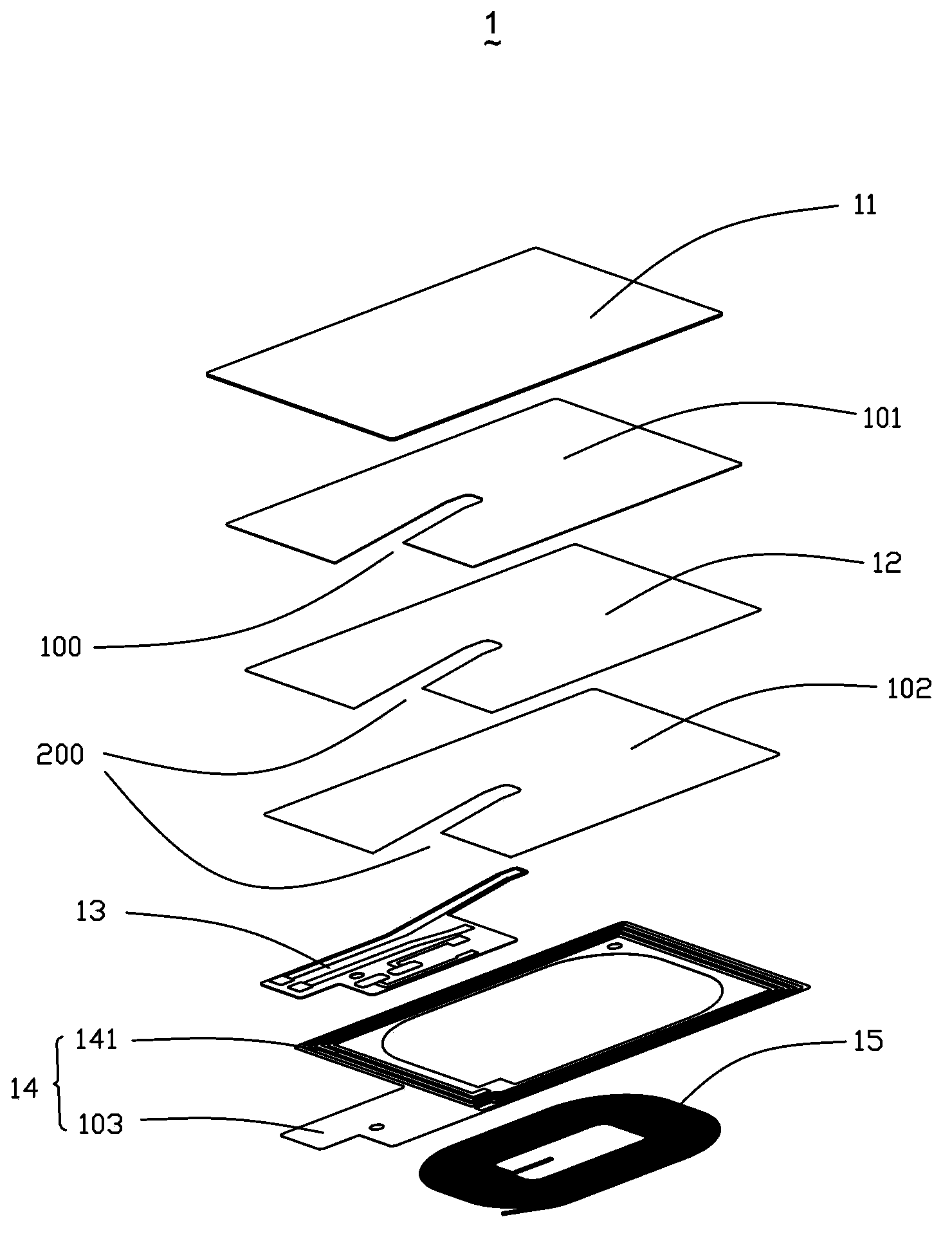
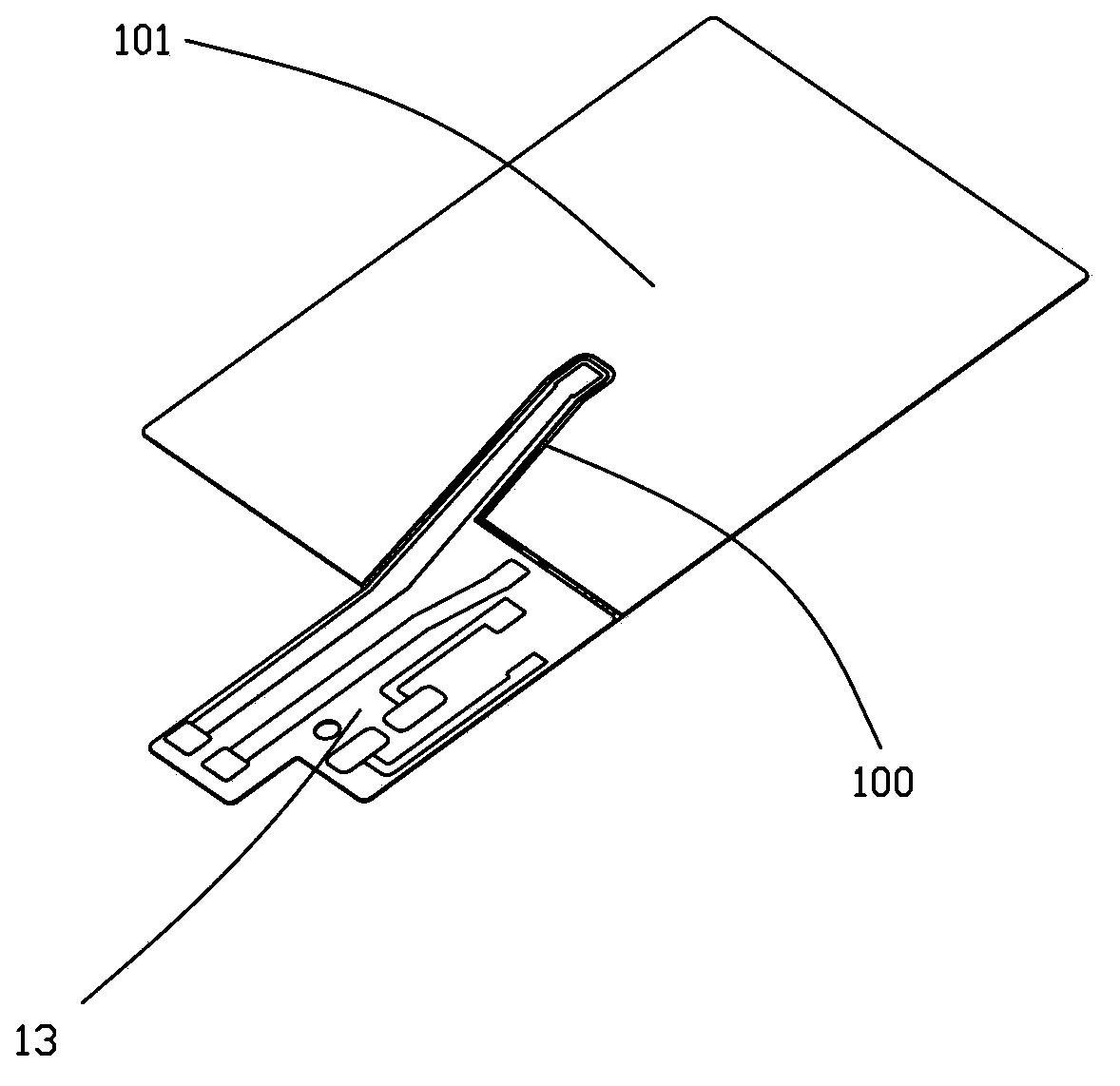
[0018] Such as figure 1 , figure 2 As shown, the antenna 1 of the present invention includes a first shielding layer 11, a first adhesive layer 101, a second shielding layer 12, a second adhesive layer 102, a flexible circuit board 13, a first coil 14 and a second coil 15. The first coil 14 is an NFC coil, and the second coil 15 is a wireless charging coil.

[0019] The first shielding layer 11 is a complete rectangular ferrite sheet, the second shielding layer 12 is also a ferrite sheet and is located directly below the first shielding layer 11, and the first adhesive layer 101 is located at the The first shielding layer 11 and the second shielding layer 12 are glued between the first shielding layer 11 and the second shielding layer 12.

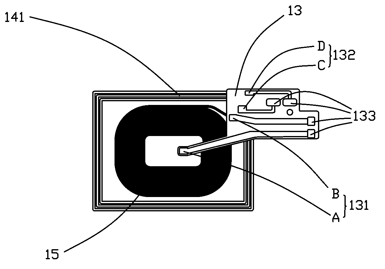
[0020] The first ring 14 is located under the second shielding layer 12 and includes an annular adhesive tape 103 and a silver-plated ...


PUM


Abstract

The invention provides an antenna comprising a first magnetic shielding layer, a second magnetic shielding layer which is arranged under the first magnetic shielding layer, a first coil and a second coil which are arranged under the second magnetic shielding layer, and a flexible printed circuit board which is connected with the first coil and the second coil. The first coil comprises an annular adhesion belt and a silver-plated pattern on the adhesion belt; the second coil is arranged in the center portion of the adhesion belt; and the second coil is provided with a gap which can enable the flexible printed circuit board to be accommodated in the gap partially. Compared with the antenna in the correlation technique, the antenna provided in the invention has relatively-small thickness and impedance.

Description

【Technical field】 [0001] The invention relates to the field of radio frequency antennas, in particular to an antenna for handheld portable devices. 【Background technique】 [0002] Wireless charging technology (Wireless charging technology; Wireless charge technology), derived from wireless power transmission technology, uses magnetic resonance to transmit charges in the air between the charger and the device, and coils and capacitors form resonance between the charger and the device. Technology that enables efficient transmission of electrical energy. With the rapid rise of battery-hungry devices such as smartphones, there is an increasing need to develop breakthrough charging technologies such as wireless charging. [0003] The antenna in the related art includes a wireless charging coil wound by a single metal wire, an NFC coil made of FPC, and an electromagnetic shielding layer. As consumers increasingly favor light and thin hand-held portable devices, this requires the...

Claims


Application Information

Patent Timeline
IPC IPC(8): H01Q1/38H01Q1/22H01Q7/04
Inventor 何宗秀
Owner AAC PRECISE MFG TECH CHANGZHOU
Why Eureka
Try Eureka