
A driving circuit for an inductive device

A technology for driving circuits and devices, applied in the field of driving circuits for inductive devices, can solve the problems of non-adjustable output voltage, high power consumption of driving circuits, restricting the scope of application, etc., to achieve stable and reliable voltage, reduce data control lines, and improve compatibility. and reliability effects

Active Publication Date: 2016-08-17
JIANGSU YINHE TONGZHI NEW ENERGY TECHNOLOGY CO LTD
View PDF7 Cites 0 Cited by
  • Summary
  • Abstract
  • Description
  • Claims
  • Application Information

AI Technical Summary

Problems solved by technology

Since the above drive circuit only plays the role of opening and closing, the output voltage is not adjustable, so that it can only be applied to electromagnets with the same working voltage, which seriously restricts its scope of application; moreover, in order to ensure the mechanical action of the electromagnet, Its output voltage is higher, which makes the power consumption of the whole drive circuit higher

Method used


Image

  • A driving circuit for an inductive device

Examples


Embodiment Construction

[0013] Below in conjunction with accompanying drawing, take driving electromagnet (its coil is L1) as example to describe the specific embodiment of the present invention in detail:

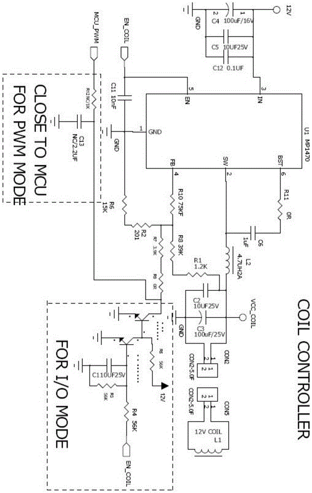
[0014] Such as figure 1 As shown, a drive circuit for an inductive device, including: a step-down DC-DC voltage conversion module U1 (model MP1470), a feedback circuit, and a switch connected to the output terminal SW (pin 2) of the DC-DC voltage conversion module U1 An output circuit, the output terminal of the output circuit is used as the output terminal VCC_COIL of the driving circuit, and the output circuit includes: an output inductor L2 arranged between the output terminal SW of the DC-DC voltage conversion module U1 and the output terminal VCC_COIL of the driving circuit , and an output filter capacitor connected in parallel to the output terminal VCC_COIL of the drive circuit and the ground wire GND by the parallel connection of the second capacitor C2 and the third capacitor C3; the fee...


PUM


Abstract

The invention discloses a drive circuit of an inductive device. The drive circuit of the inductive device comprises a DC-DC voltage conversion module, a feedback circuit and an output circuit connected with the output end of the DC-DC voltage conversion module. The output end of the output circuit serves as the output end of the drive circuit. The feedback circuit comprises a bleeder circuit arranged between the output end of the output circuit and a ground wire and a gain adjusting resistor arranged between the output end of the bleeder circuit and the feedback input end of the DC-DC voltage conversion module. The output end of the bleeder circuit is connected with one end of a constraint adjusting resistor and the other end of the constraint adjusting resistor is connected with a low-pass filtering circuit and / or an electric level constraint adjusting circuit in parallel, the input end of the low-pass filtering circuit is used for being connected with pulse width modulation signals, the control end of the electric level constraint adjusting circuit is connected with a delayed shutoff circuit, and the control end of the delayed shutoff circuit is used for being connected with on-off control signals. The drive circuit is particularly suitable for driving an electromagnet.

Description

technical field [0001] The present invention relates to a driving circuit, in particular to a driving circuit for inductive devices such as electromagnets. Background technique [0002] At present, the drive circuit of traditional inductive devices such as electromagnets has a relatively simple structure, and usually only includes an output circuit (usually composed of MOS transistors). The output terminal of the circuit is connected with the control terminal of the electromagnet coil. People in the industry know that when the electromagnet is started, a large current is required to ensure the mechanical action of the electromagnet, so a high voltage is required (for an electromagnet with a rated working voltage of 12V, the starting voltage is usually not lower than 10.4V ); However, when the electromagnet is in place, only a small current is required to keep the electromagnet in the state of attraction. At this time, usually only a small holding voltage (usually not lower ...

Claims


Application Information

Patent Timeline
Patent Type & Authority Patents(China)
IPC IPC(8): H02M3/00H01F7/18
Inventor 汤栋良吴建明薛利军顾洪春徐成
Owner JIANGSU YINHE TONGZHI NEW ENERGY TECHNOLOGY CO LTD
Learn More