Motor restarting controller

A controller and restart technology, applied in the direction of starter components, etc., to achieve the effect of solving the problem of contactor release and response time without dead zone

Active Publication Date: 2014-07-09
SHENZHEN BEITON CONTROL TECH
View PDF4 Cites 6 Cited by
  • Summary
  • Abstract
  • Description
  • Claims
  • Application Information

AI Technical Summary

Problems solved by technology

[0005] In view of this, the technical problem to be solved by the present invention is to provide a motor restart controller to solve the problem of realizing a quick response to the instantaneous voltage loss of the power supply through a non

Method used


Image

  • Motor restarting controller
  • Motor restarting controller
  • Motor restarting controller

Examples


Embodiment 1

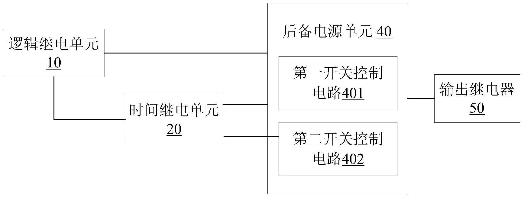
[0028] like figure 1 As shown, a motor sloshing restart controller provided by the embodiment of the present invention includes a logic relay unit 10, a time relay unit 20, a backup power unit 40 and an output relay 50, and the time relay unit 20 and the backup power unit 40 and the output relay 50 are respectively connected with the backup power supply unit 40, wherein:

[0029] Logic relay unit 10, its pair of power supply terminals are respectively connected with live wire and neutral wire to detect the instantaneous sag amplitude of power supply voltage, and its pair of input terminals are connected with normally open auxiliary contact of contactor or inverter running signal contact to detect contact The state of the inverter or the frequency converter; when it is detected that the normally open auxiliary contact of the contactor or the running signal contact of the frequency converter is disconnected, the output contact of the control output relay 50 is closed instantaneo...

Embodiment 2

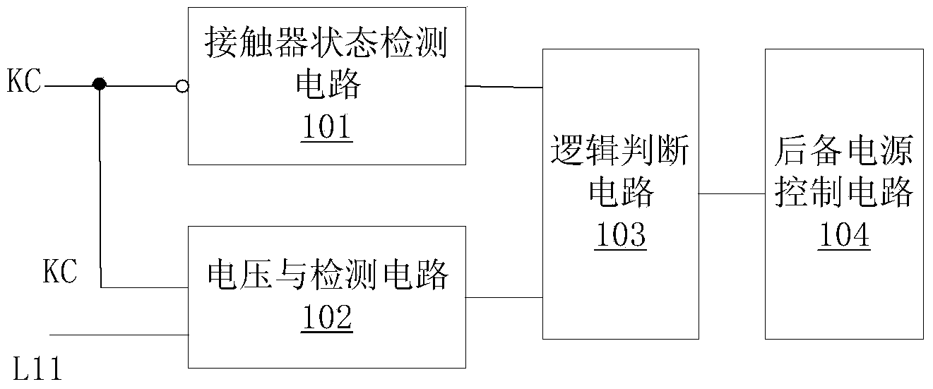
[0039] like figure 2 As shown, a logic relay unit 10 provided by a preferred embodiment of the present invention includes a voltage detection circuit 101, a contactor state detection circuit 102, a logic judgment circuit 103 and a backup power supply control circuit 104, wherein:

[0040]The input terminal of the voltage detection circuit 101 is connected to the live line and neutral line of the control power supply, detects the instantaneous sag amplitude of the power supply voltage, and outputs it to the logic judgment circuit 103 . Among them, the voltage of the control power supply can be 220Vac (plug-in type) or 380V (fixed type).

[0041] The contactor state detection circuit 102 is connected to the input end of the normally open auxiliary contact of the contactor or the running signal contact of the frequency converter, detects the state of the normally open auxiliary contact of the contactor or the running signal contact of the frequency converter, and outputs it to t...

Embodiment 3

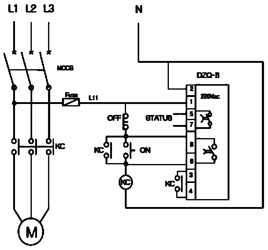
[0047] Such as image 3 Shown is the example wiring diagram of the present invention applied to the contactor, in the figure, three-phase coils L1, L2, L3, three-phase circuit breaker MCCS, fuse Fuse, contactor KC and motor M form the main circuit, and the motor restarts The controller DZQ-B is connected in parallel in the controller of the contactor KC, and DZQ-B includes 8 contacts, among which:

[0048] The first contact and the second contact: they are the power terminals of the logic relay unit of DZQ-B. The first contact is connected to the live wire L11 of the control power supply as the input power of DZQ-B; the second contact is connected to the neutral line, considering the impact on electronic devices Protection, the second contact should be reliably grounded. The docking point is also the detection point for detecting the change of the power supply voltage of L11, and collects and detects the instantaneous sag amplitude of the power supply voltage.

[0049] The t...


PUM


Abstract

The invention discloses a motor restarting controller, and belongs to the technical field of industrial control. The motor restarting controller comprises a logic relay unit, a time relay unit, a standby power source unit and an output relay. The logic relay unit controls the instant closing of an output contact of the output relay when the opening moment of a normally-open auxiliary contact of a contactor or an operation signal contact of a frequency converter is detected. If the detected instant sunken amplitude of a power source voltage reaches to the preset amplitude before the opening of the auxiliary contact of the contactor or the opening of the operation signal contact of the frequency converter, the time relay unit controls the action mode of the output contact to be instant closing and delay opening within the allowed voltage-reducing time limit by controlling the opening or closing of a standby power source switch of the output relay within the preset allowed voltage-missing time limit.

Description

technical field [0001] The invention relates to the technical field of industrial control, in particular to a motor restart controller. Background technique [0002] AC contactors and frequency converters are commonly used in modern industrial low-voltage motor control circuits. Its characteristics are self-maintaining when charged, and release without pressure. However, when the motor encounters a momentary power loss during normal operation, it will cause the release of the contactor and the low-voltage protection trip of the inverter. Interruption will cause great economic losses to continuous production enterprises such as petroleum, petrochemical, chemical, electric power, and metallurgy, and even lead to safety accidents. [0003] With the ring network of the main power grid and the increase of power supply lines of the medium-voltage power grid of the enterprise, and the enterprise does not set up impedance isolation components to reduce power consumption, it is inev...

Claims


Application Information

Patent Timeline
IPC IPC(8): H02P1/10
CPCH02P1/10
Inventor 金凯程涛
Owner SHENZHEN BEITON CONTROL TECH
Why Eureka
Try Eureka