Motor restarting controller
A controller and restart technology, applied in the direction of starter components, etc., to achieve the effect of solving the problem of contactor release and response time without dead zone
- Summary
- Abstract
- Description
- Claims
- Application Information
AI Technical Summary
Problems solved by technology
Method used
Image
Examples
Embodiment 1
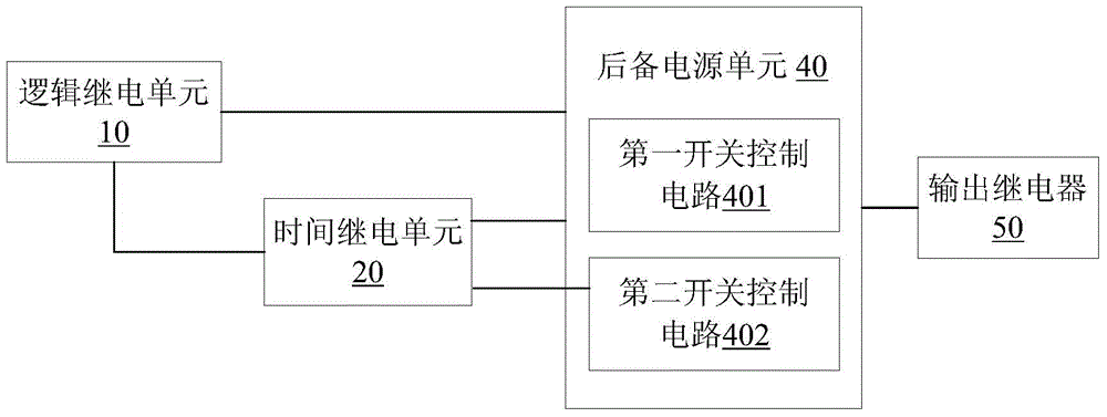
[0028] like figure 1 As shown, a motor sloshing restart controller provided by the embodiment of the present invention includes a logic relay unit 10, a time relay unit 20, a backup power unit 40 and an output relay 50, and the time relay unit 20 and the backup power unit 40 and the output relay 50 are respectively connected with the backup power supply unit 40, wherein:
[0029] Logic relay unit 10, its pair of power supply terminals are respectively connected with live wire and neutral wire to detect the instantaneous sag amplitude of power supply voltage, and its pair of input terminals are connected with normally open auxiliary contact of contactor or inverter running signal contact to detect contact The state of the inverter or the frequency converter; when it is detected that the normally open auxiliary contact of the contactor or the running signal contact of the frequency converter is disconnected, the output contact of the control output relay 50 is closed instantaneo...
Embodiment 2
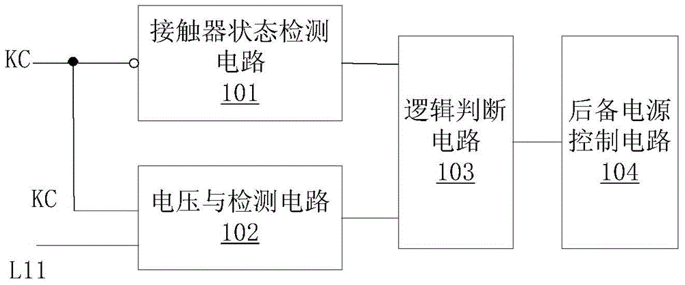
[0039] like figure 2 As shown, a logic relay unit 10 provided by a preferred embodiment of the present invention includes a voltage detection circuit 101, a contactor state detection circuit 102, a logic judgment circuit 103 and a backup power supply control circuit 104, wherein:
[0040]The input terminal of the voltage detection circuit 101 is connected to the live line and neutral line of the control power supply, detects the instantaneous sag amplitude of the power supply voltage, and outputs it to the logic judgment circuit 103 . Among them, the voltage of the control power supply can be 220Vac (plug-in type) or 380V (fixed type).
[0041] The contactor state detection circuit 102 is connected to the input end of the normally open auxiliary contact of the contactor or the running signal contact of the frequency converter, detects the state of the normally open auxiliary contact of the contactor or the running signal contact of the frequency converter, and outputs it to t...
Embodiment 3
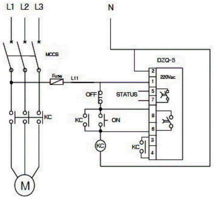
[0047] like image 3 Shown is the example wiring diagram of the present invention applied to the contactor, in the figure, three-phase coils L1, L2, L3, three-phase circuit breaker MCCS, fuse Fuse, contactor KC and motor M form the main circuit, and the motor restarts The controller DZQ-B is connected in parallel in the controller of the contactor KC, and DZQ-B includes 8 contacts, among which:
[0048] The first contact and the second contact: they are the power terminals of the logic relay unit of DZQ-B. The first contact is connected to the live wire L11 of the control power supply as the input power of DZQ-B; the second contact is connected to the neutral line, considering the impact on electronic devices Protection, the second contact should be reliably grounded. The docking point is also the detection point for detecting the change of the power supply voltage of L11, and collects and detects the instantaneous sag amplitude of the power supply voltage.
[0049] The thir...
PUM
 Abstract
Description
Claims
Application Information
 - R&D
- Intellectual Property
- Life Sciences
- Materials
- Tech Scout
- Unparalleled Data Quality
- Higher Quality Content
- 60% Fewer Hallucinations
Browse by: Latest US Patents, China's latest patents, Technical Efficacy Thesaurus, Application Domain, Technology Topic, Popular Technical Reports.
© 2025 PatSnap. All rights reserved.Legal|Privacy policy|Modern Slavery Act Transparency Statement|Sitemap|About US| Contact US: help@patsnap.com


