Wire harness with protective member
A technology for protecting components and wire harnesses, which is applied in the field of wire harnesses, can solve problems such as long wire harness wiring paths, and achieve the effects of improving protection functions, reducing manufacturing costs, and improving operability
- Summary
- Abstract
- Description
- Claims
- Application Information
AI Technical Summary
Problems solved by technology
Method used
Image
Examples
no. 1 example
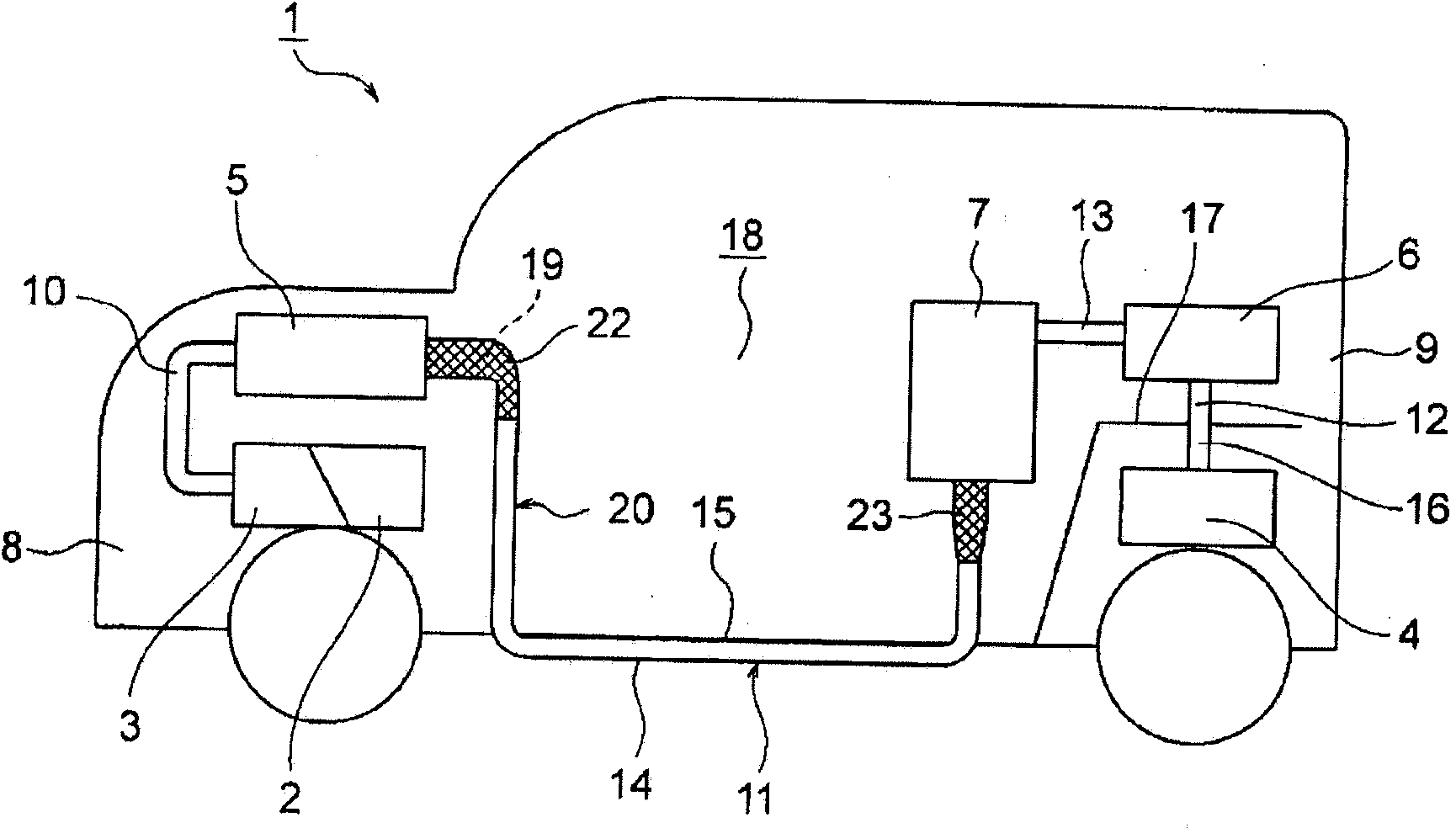
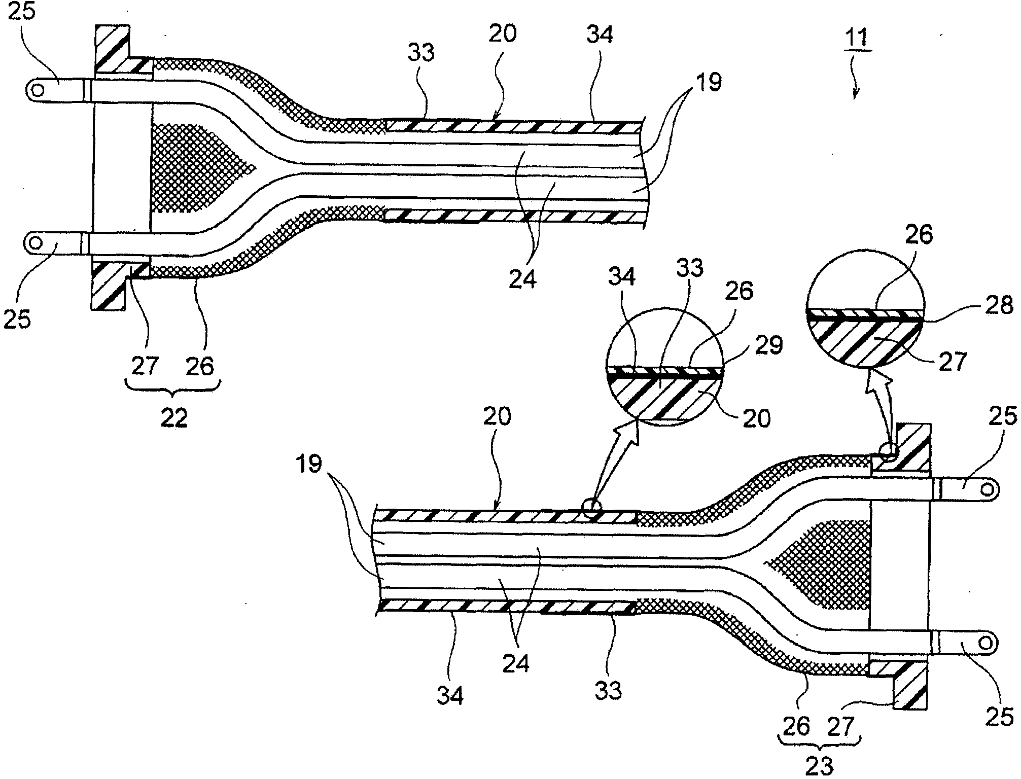
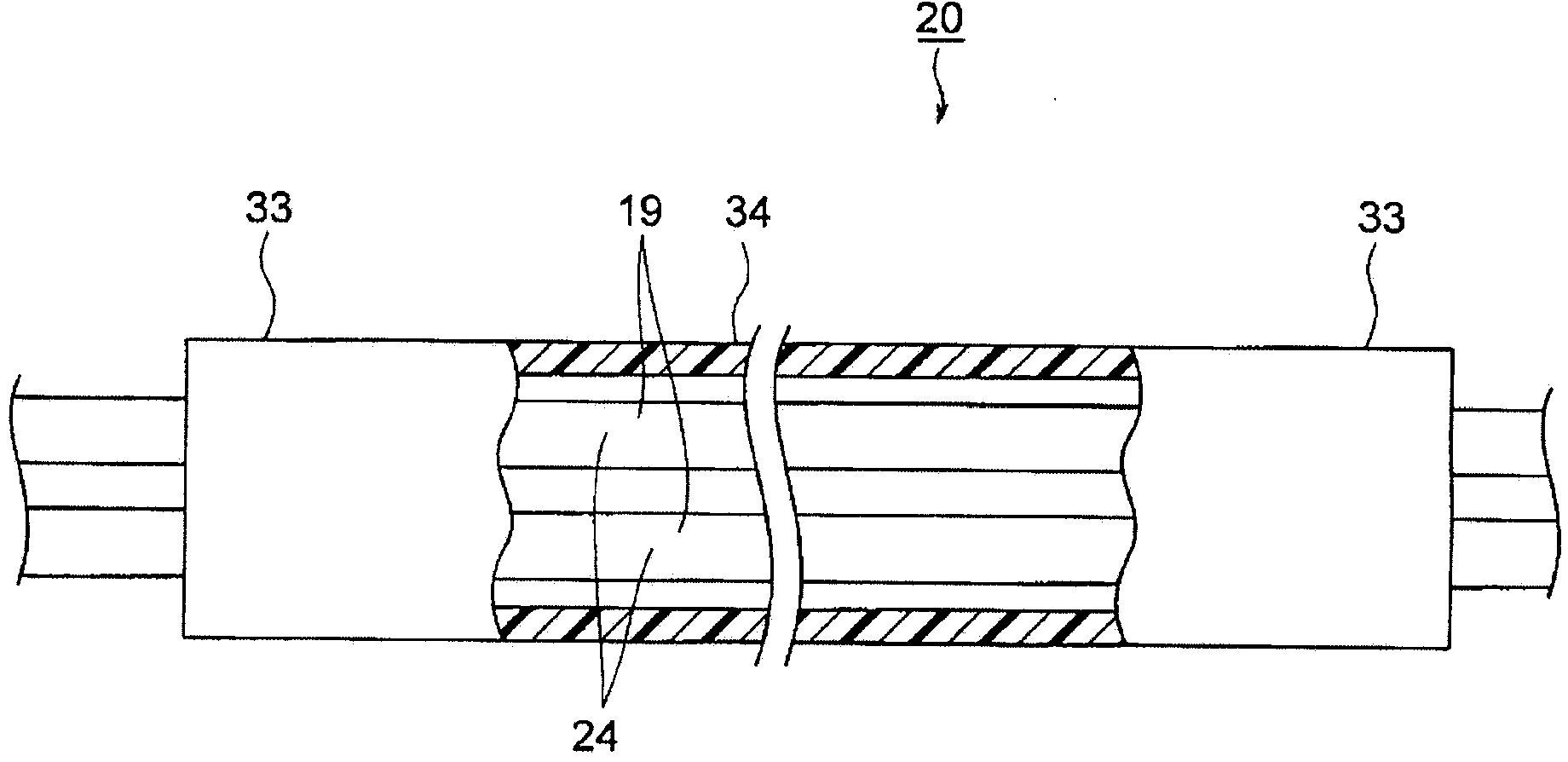
[0062] Next, a first embodiment will be described with reference to the drawings. figure 1 is a schematic diagram of a vehicle in which the wire harness according to the first embodiment of the present invention is routed. figure 2 is a cross-sectional view showing the structure of the wire harness. image 3 is a sectional view showing the structure of the protection member.
[0063] In the following description, specific shapes, materials, numerical values, directions, etc. are exemplified to facilitate understanding of the present invention, and may be appropriately changed depending on applications, objects, specifications, etc.
[0064] In the first embodiment, an example of applying the wire harness intermediate member and the wire harness to a hybrid vehicle (also an electric vehicle) is given and described.
[0065] figure 1A hybrid vehicle 1 is shown. A hybrid vehicle 1 is a vehicle driven together by using an engine 2, a front motor unit 3, and a rear motor unit ...
no. 2 example
[0085] Next, a second embodiment will be described with reference to the drawings. Figure 4 is a cross-sectional view showing the structure of the wire harness. Figure 5 is a cross-sectional view showing the structure of the protection member.
[0086] The second embodiment is the same as the first embodiment except that an insulating resin covering 32 described below is provided on the outer surface 34 of the protective member 20 of the wire harness 11 in the first embodiment. Therefore, the insulating resin covering 32 will be described below.
[0087] exist Figure 4 with 5 In the second embodiment, an insulating resin covering 32 is further formed on the outer surface 34 of the protective member 20 of the wire harness 31 . The insulating resin covering 32 is formed as a layer corresponding to the upper layer of the protective member 20, and is made of a resin composition having insulating properties. After the protective member 20 is molded, the insulating resin cov...
no. 1 example 1
[0090] exist Figure 4 Among them, each of one ends of the braids 26 constituting the parts of the terminal shield members 22 and 23 is connected to the outer peripheral surface of the shield case 27, and the other ends of the braids 26 are respectively connected to the shield member connection portions 35 of the protection member 20. . In this embodiment, the connection of the braid 26 and the shield member connection portion 35 should be performed by welding. This should be the instance. The braid 26 and the shield connection part 35 are connected and fixed by the connection part 29 formed between the braid 26 and the shield connection part 35 . Like the first embodiment, a braid formed by weaving conductive resin fibers into a mesh shape and a shield formed of a conductive resin composition can be used as the braid 26 and the shield 27 in this embodiment. This should be instance.
[0091]In the present embodiment, the terminal shield members 22 and 23 can be connected a...
PUM
 Abstract
Description
Claims
Application Information
 - R&D
- Intellectual Property
- Life Sciences
- Materials
- Tech Scout
- Unparalleled Data Quality
- Higher Quality Content
- 60% Fewer Hallucinations
Browse by: Latest US Patents, China's latest patents, Technical Efficacy Thesaurus, Application Domain, Technology Topic, Popular Technical Reports.
© 2025 PatSnap. All rights reserved.Legal|Privacy policy|Modern Slavery Act Transparency Statement|Sitemap|About US| Contact US: help@patsnap.com


