[0003] However, the
metal rods used in the above-mentioned
fusion surgery cannot be elastically bent and stretched, so the fixed and fused multi-segmented vertebral bodies can no longer swing and bend. A normal
intervertebral disc must bear all the effects of human movement
[0004] In order to improve the above problems, U.S. Patent No. 8,080,038 discloses a double-layer spring rod fixed between several vertebrae. In addition to releasing pressure at the
lesion to reduce the pain of the patient, the double-layer spring member can be used to pull The stretching and bending characteristics provide the vertebral bodies of the vertebrae, which can swing or bend with the direction of motion; however, when the patient jumps or runs, the sudden upward and downward force will The double-layer spring member is relatively compressed in the axial direction, which may cause the
lesion to be compressed again and cause pain
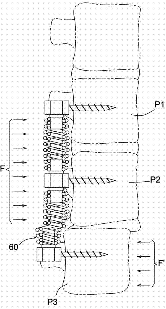
In addition, as attached to the present invention figure 1 As shown, in this case, since the double-layer spring member 60 composed of wire rods is wound in spiral coils, the adjacent spring coils cannot bear relatively large radial relative forces F, F', and it is very easy to cause the relative radial force Forces F, F', resulting in figure 1 The state of relative deviation shown, that is, the spine stabilization device disclosed in this case, does not have the function of protection against radial relative force, so when the
human body moves or is subjected to external force, it is very easy for the double-layer spring member to The multi-segmented vertebral bodies P1, P2, and P3 corresponding to 50 have relative offsets and dislocations, resulting in greater damage to the body of the lesion
[0005] For this reason, as shown in US Publication No. US2007 / 0049937A1, the middle section of a rod-shaped
implant element 1 (The rod-shaped
implant element), such as the embodiment of fig.6-13, is formed with a spiral groove 10 Make it a bendable flexible segment, and at the two ends of the longitudinally long rod-shaped
implant component 1, end plugs 13, 14 (closure member) are locked or riveted, and the longitudinally long rod-shaped implant component 1 is pierced with a core rod 12. In this embodiment, although the purpose of preventing deviation can be achieved by the core rod 12, the elongated rod-shaped implant component 1 is manufactured, such as directly on the hollow
pipe.
Cutting the spiral groove 10, because the thickness of the
pipe wall is thin, the
processing force will often cause the deformation of the hollow
pipe. Therefore, the usual manufacturing method is to
cut the spiral groove 12 on a
solid rod first, and then
cut the spiral groove 12 from one end of the rod. , give milling
processing, and make the
cut hole pass through the spiral groove 12, so that the through spiral groove 12 is formed on the rod-shaped implant component 1, and then, at the two ends of the rod-shaped implant component 1, respectively apply Pre-processing to form screw holes for locking the end plugs 13, 14; therefore, the rod-shaped implant component 1 disclosed in the prior art must go through four
machining processes, which makes the processing difficult and complicated. also increases the cost
In addition, because the device implanted into the
human body does not allow burrs or sharp edges caused by processing, it makes the rod-shaped implant
assembly 1 more difficult to manufacture and process.
[0006] In addition, as shown in US Patent No. 7,329,258, the structure provided by it, its first
elastic component 2, is the same as the above-mentioned previous proposal, which is formed by
machining a
solid rod body, and must also be machined many times. The process increases the difficulty and complexity of processing, and also increases the cost, which shows the need for improvement
[0007] In the above two cases of US2007 / 0049937A1 and No. 7,329,258, since the formed rod-shaped implant component 1 or the first
elastic component 2 is formed with a spiral groove by a cutter, since the spiral groove has a certain
groove width, the rod The shaped implant component 1 or the first
elastic component 2 can be compressed axially, which is not suitable for spinal patients injured by compression. The above two solutions cannot effectively
resist the relative
axial force, that is, they cannot effectively support the injured spine. spine, and there is a clear need for improvement

