Triethylene glycol furnace exhaust recycling system and method for producing slices

An exhaust gas recovery and triethylene glycol technology, applied in separation methods, chemical instruments and methods, vapor condensation, etc., can solve problems such as unfavorable health of operators, pollution of surrounding air, and high irritation, so as to ensure physical health, The effect of reducing pollution and improving utilization

Inactive Publication Date: 2014-07-16
许燕红
View PDF0 Cites 0 Cited by
  • Summary
  • Abstract
  • Description
  • Claims
  • Application Information

AI Technical Summary

Problems solved by technology

Triethylene glycol furnace is an indispensable chemical equipment for polyester production enterprises. The existing triethylene glycol furnace has an exhaust port. The temperature in the furnace is relatively high, and triethylene glycol volatilizes to form triethylene glycol waste gas. During the production process, three Glycol exhaust gas is directly discharged from the exhaust port, the smell is very strong and irritating, it is easy to cause ambient air pollution, which is not conducive to the health of operators

Method used


Image

  • Triethylene glycol furnace exhaust recycling system and method for producing slices

Examples


Embodiment 1

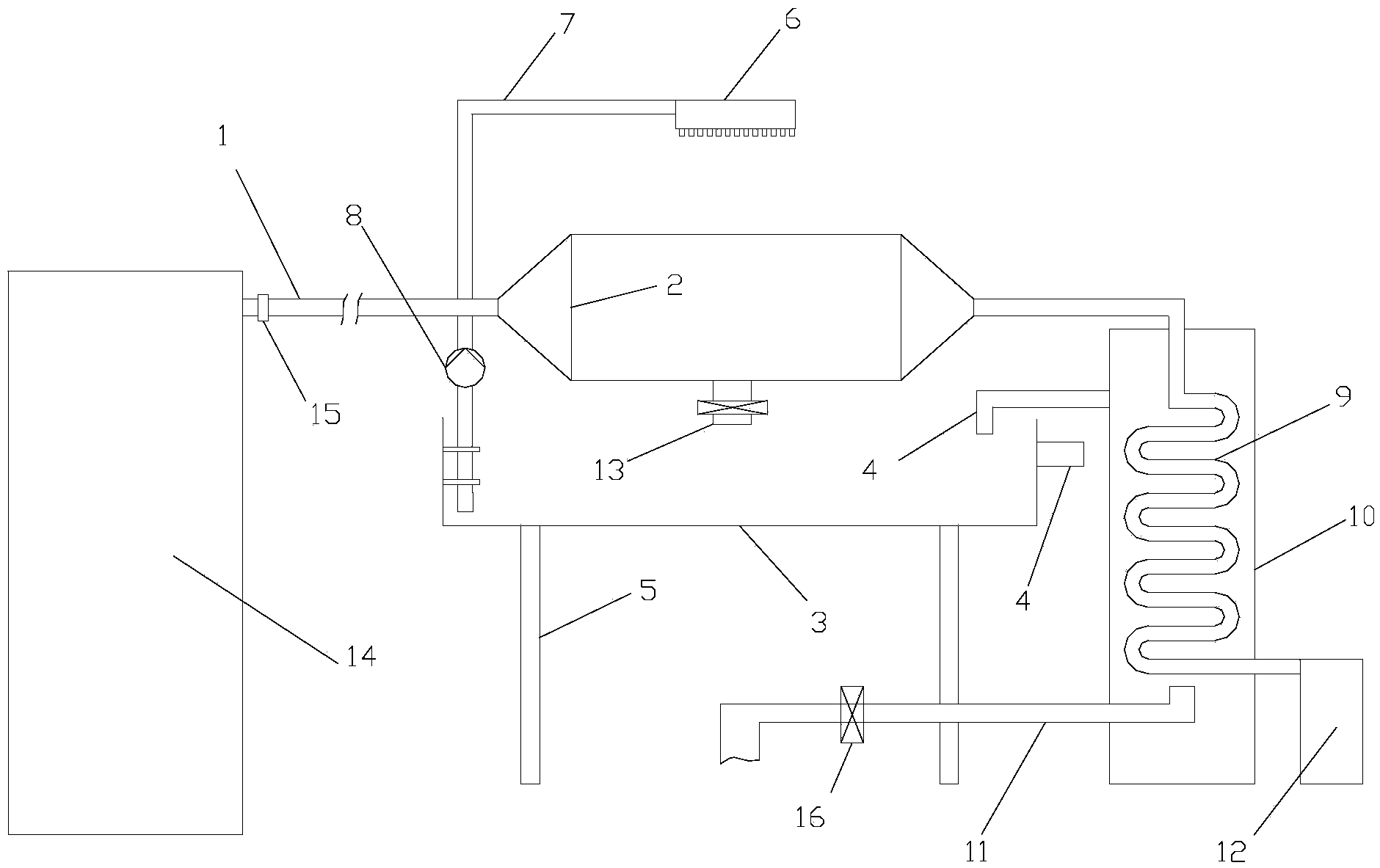
[0012] Such as figure 1 As shown, the triethylene glycol furnace exhaust gas recovery system for slice production described in this embodiment includes a triethylene glycol furnace 14, and the exhaust port 15 of the triethylene glycol furnace 14 is connected with an outlet pipe 1, and also includes A cooling chamber 2 with tapered ends, the bottom of the cooling chamber 2 is provided with a condensate outlet 13, a water collection tank 3 is provided below the cooling chamber 2, an overflow pipe 4 is arranged on the water collection tank 3, and the bottom of the water collection tank 3 A bracket 5 is provided, and a spraying device 6 is provided above the cooling chamber 2, and the spraying device 6 is connected with a suction pipe 7 that goes deep into the sump 3. During the spraying process of the spraying device 6 from above to the water, Part of the heat of the water can be dissipated to reduce the temperature of the spray water, and a water pump 8 is provided on the suctio...

Embodiment 2

[0016] This embodiment discloses a method for recovering exhaust gas from a triethylene glycol furnace produced by slicing. The method adopts the exhaust gas recovery system of a triethylene glycol furnace described in Example 1, and is characterized in that: triethylene glycol gas is condensed in the cooling chamber to form Liquid triethylene glycol, the non-condensed triethylene glycol gas in the cooling chamber continues to enter the cooling coil for cooling, the cooling coil is located in the water tank, the temperature of the cooling coil is controlled by continuously injecting cooling water into the water tank, so that It achieves a stable cooling effect, and finally the cooled liquid triethylene glycol flows into the condensation tank.


PUM


Abstract

The invention discloses a triethylene glycol furnace exhaust recycling system for producing slices. The triethylene glycol furnace exhaust recycling system comprises a triethylene glycol furnace and a cooling cavity, wherein a condensate outlet is formed in the bottom of the cooling cavity; a water collecting tank is arranged below the cooling cavity; an overflow pipe is arranged on the water collecting tank; a bracket is arranged below the water collecting tank; a spraying device is arranged above the cooling cavity; the other end of the cooling cavity is connected with a cooling coil; the cooling coil is arranged in a water tank; the bottom of the cooling coil is connected with a condensing tank outside the water tank. The invention discloses a triethylene glycol furnace exhaust recycling method for producing the slices. The triethylene glycol furnace exhaust recycling system and method have the advantages that triethylene glycol gas is discharged from a triethylene glycol furnace gas outlet, and enters the cooling cavity to be cooled through an escape pipe; liquid triethylene glycol flows outside from the condensate outlet; uncondensed triethylene glycol gas inside the cooling cavity continues to enter the cooling coil to be cooled; finally, the cooled liquid triethylene glycol flows inside the condensing tank, and can be recycled.

Description

technical field [0001] The invention relates to an exhaust recovery system used in the chemical fiber industry, in particular to a triethylene glycol furnace exhaust recovery system for slicing production. Background technique [0002] With the continuous development of the chemical fiber industry, chemical fiber enterprises must constantly improve their product quality and reduce costs in order to gain a foothold in the market. Now the chemical fiber industry plays an important role in the production process of chips. Triethylene glycol furnace is an indispensable chemical equipment for polyester production enterprises. The existing triethylene glycol furnace has an exhaust port. The temperature in the furnace is relatively high, and triethylene glycol volatilizes to form triethylene glycol waste gas. During the production process, three Glycol exhaust gas is directly discharged from the exhaust port, and the smell is very strong and irritating, which is likely to cause am...

Claims


Application Information

Patent Timeline
IPC IPC(8): B01D53/00B01D5/00
Inventor 许燕红
Owner 许燕红
Why Eureka
Try Eureka