Machining method of wheel groove semi-finish milling cutter

A processing method and semi-finishing milling technology, which are applied in the processing field of semi-finishing milling cutters for wheel groove milling cutters, can solve problems such as the inability to guarantee machining accuracy and machining efficiency, achieve optimal cutting allowance distribution and machining parameters, improve service life, The effect of improving processing efficiency

Active Publication Date: 2014-07-16
HARBIN TURBINE +1
View PDF9 Cites 6 Cited by
  • Summary
  • Abstract
  • Description
  • Claims
  • Application Information

AI Technical Summary

Problems solved by technology

[0004] In order to solve the problem that the existing wheel groove semi-finish milling cutter processing method cannot guarantee the proce

Method used


Image

  • Machining method of wheel groove semi-finish milling cutter
  • Machining method of wheel groove semi-finish milling cutter
  • Machining method of wheel groove semi-finish milling cutter

Examples


specific Embodiment approach 1

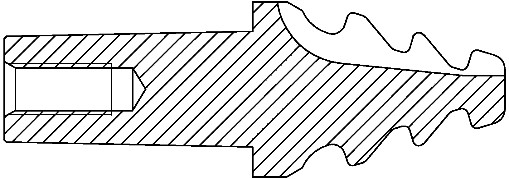
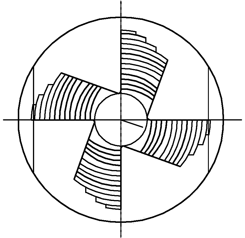
[0029] Specific implementation mode one: combine Figure 1-Figure 5 Describe the present embodiment, the wheel groove semi-finishing milling cutter machining method of the present embodiment is realized according to the following steps:

[0030] Step 1. Turning each part of the semi-finishing milling cutter on the ordinary lathe: Brown Sharp No. 9 taper 0.6 ~ 0.7mm, 16°48′ tapered single side 1.5mm, leave Φ10×10 auxiliary head at the right end, and hit the center Hole d=2mm, 0.5″ thread turning at the left end, hole chamfering 60°, turning parameters: speed 400r / min, feed rate 0.3mm / r, turning depth 1.5mm;

[0031] Step 2. Turning the wheel groove semi-finishing milling cutter profiles on the CNC lathe: each profile line is 0.4mm along the normal direction; wherein, the turning parameters are: speed 500r / min, feed rate 0.2mm / r, turning Depth 0.5mm;

[0032] Step 3. Milling wheel slot semi-finishing cutter tooth alignment on CNC milling machine: Turning parameters are: speed ...

specific Embodiment approach 2

[0043] Specific embodiment 2: The difference between this embodiment and specific embodiment 1 is: the heat treatment process in step 6 is: first preheat for 2 hours, the preheating temperature is 550 ° C, then put it in a medium temperature furnace to heat for 30 minutes at 850 ° C, and then put it at a high temperature Heat in the furnace at 1200°C for 15 minutes, then put it in the isothermal furnace at 600°C for 30 minutes, and finally put it in the tempering furnace at 550°C for 3 times, 2 hours each time. Other steps and parameters are the same as those in Embodiment 1.


PUM


Abstract

The invention relates to a machining method of a wheel groove milling cutter, and discloses a machining method of a wheel groove semi-finish milling cutter. The machining method of the wheel groove semi-finish milling cutter solves the problems that an existing machining method of the wheel groove semi-finish milling cutter can not ensure machining precision and machining efficiency. Molded lines of the wheel groove semi-finish milling cutter are turned on a numerically controlled milling machine; tooth benchmarks of the wheel groove semi-finish milling cutter are milled on the numerically controlled milling machine; tooth back steps of the wheel groove semi-finish milling cutter are milled on the numerically controlled milling machine; 35-flat neck benchmarks of the wheel groove semi-finish milling cutter are milled on a horizontal milling machine; the wheel groove semi-finish milling cutter is hardened to be HRC66-68 in a quenching mode; a Brown and Sharpe NO.9 taper benchmark of the wheel groove semi-finish milling cutter is ground on a cylindrical grinder; the grinder cuts off an auxiliary head of the wheel groove semi-finish milling cutter, and rubs down the end face of the wheel groove semi-finish milling cutter; a five-axis numerically controlled grinder grinds a front corner, a wave blade form and a rear corner of the wheel groove semi-finish milling cutter; after the wheel groove semi-finish milling cutter is machined, the wheel groove semi-finish milling cutter is coated with an AlTiN coating; the wheel groove semi-finish milling cutter is lettered and packaged. The method is used for machining the wheel groove semi-finish milling cutter.

Description

technical field [0001] The invention relates to a processing method of a wheel groove milling cutter semi-finishing milling cutter. Background technique [0002] The wheel groove milling cutter is a special tool for processing the wheel groove of the steam turbine rotor. Each wheel groove profile is processed by the wheel groove rough milling cutter, the wheel groove semi-finishing cutter and the wheel groove fine milling cutter. The wheel groove semi-finishing cutter (such as figure 1 (shown) shows that after the groove rough milling cutter is grooved, the rough milling wheel groove cutter leaves a certain machining allowance for the wheel groove fine milling cutter, and the wheel groove semi-finishing cutter is used in batches, and the wheel groove semi-finishing cutter is processed At this time, the machining accuracy and machining efficiency cannot be guaranteed. Therefore, a machining method for semi-finishing milling cutters for wheel grooves has been developed and opt...

Claims


Application Information

Patent Timeline
IPC IPC(8): B23P15/34
CPCB23P15/34
Inventor 刘剑孙盛丽赵祎昕
Owner HARBIN TURBINE
Why Eureka
Try Eureka