Sand lifting and energy storing power station

A technology of energy storage power station and sand bank, which is applied in the direction of machines/engines, mechanical equipment, engines, etc., can solve the problems of low carrying capacity, difficult loading and unloading, and high energy consumption, so as to achieve strong energy storage capacity and power generation capacity, and save time The effect of low labor cost and strong cargo carrying capacity

Inactive Publication Date: 2014-07-16
LANZHOU UNIVERSITY OF TECHNOLOGY
View PDF5 Cites 7 Cited by
  • Summary
  • Abstract
  • Description
  • Claims
  • Application Information

AI Technical Summary

Problems solved by technology

[0005] 1. The carrying capacity of the aerial ropeway is low
Aerial ropeways rely on steel wire ropes to support and pull trucks, and rely on supports and supporting wheels to support steel wire ropes. Generally, the distance between supports is large, and the carrying capacity of a single truck is lower than that of rail-type trucks. Therefore, the energy storage and power generation capacity of the cableway based on it is relatively small. , not suitable for building into a large energy storage power station
[0006] 2. The automatic loading and unloading devices at both ends of the cableway are complex, costly, difficult to load and unload, time-consuming, power-consuming, and inefficient
If the automatic loading and unloading devices at both ends of the cableway can be successfully operated, the position of one end is relatively fixed, and the other end will adjust the storage position and storage height according to the amount of goods stored, and the frequency of storing goods will also change at any time. The device requires complex and intelligent devices and operating equipment, and its construction and

Method used


Image

  • Sand lifting and energy storing power station
  • Sand lifting and energy storing power station
  • Sand lifting and energy storing power station

Examples


Embodiment 1

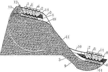
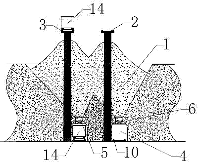
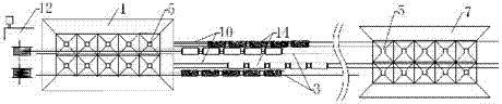
[0029] like figure 1 , figure 2 , image 3 As shown, both the high-level sand bank 1 and the low-level sand bank 7 are inclined, and two rows of sand buckets in the shape of an inverted pyramid are arranged at the bottom of the bank along the narrow and long direction, and a sand leakage port 5 is provided at the tip of the sand bucket. The number of every row of sand buckets 5 is 5, the first tunnel 4 and the second tunnel 9 are double-hole tunnel groups, a row of sand leaks 5 are provided directly above each tunnel, and the ends of the two tunnels are connected to each other. China Unicom.

[0030] Both the first track 3 and the second track 10 are double-track, and the first track 3 and the second track 10 are independent of each other.

[0031] The power and transmission system in the ground cable car sand lifting device 12 and the ground cable car power generation device 13 are independent of each other, and the cable car 14 running mode in the ground cable car sand l...

Embodiment 2

[0034] like figure 1 , figure 2 , image 3 As shown, the high-level sand bank 1 and the low-level sand bank 7 are both horizontal, and 4 rows of inverted pyramid-shaped sand buckets are arranged along the narrow and long direction at the bottom of the tank, and a sand leakage port 5 is provided at the tip of the sand bucket. The number of sand buckets 5 in each row is 20, the first tunnel 4 and the second tunnel 9 are double-hole tunnel groups, and 2 rows of sand leakage outlets 5 are arranged side by side directly above each tunnel, and the ends of the two tunnels are interconnected.

[0035] Both the first track 3 and the second track 10 are double-track, and the first track 3 and the second track 10 are independent of each other.

[0036] The power and transmission system in the ground cable car sand lifting device 12 and the ground cable car power generation device 13 are independent of each other, and the cable car 14 running mode in the ground cable car sand lifting ...

Embodiment 3

[0039] like figure 1 , figure 2 , image 3 As shown, both the high-level sand bank 1 and the low-level sand bank 7 are inclined, and two rows of sand buckets in the shape of an inverted pyramid are arranged at the bottom of the bank along the narrow and long direction, and a sand leakage port 5 is provided at the tip of the sand bucket. The number of sand buckets 5 in each row is 10, the first tunnel 4 and the second tunnel 9 are single-hole tunnels, and a row of sand leaks 5 is provided directly above each tunnel, and the ends of the two tunnels are interconnected of.

[0040] Both the first track 3 and the second track 10 are monorail tracks with staggered lanes in the middle, and the first track 3 and the second track 10 are independent of each other.

[0041] The power and transmission system in the ground cable car sand lifting device 12 and the ground cable car power generation device 13 are independent of each other, and the cable car 14 running mode in the ground c...


PUM


Abstract

The invention discloses a sand lifting and energy storing power station, and aims to change intermittent input electric energy into electric energy which can be stably output and is convenient to use by increasing and lowering the height of quicksand. A bridge (2) is built above a high-position sand warehouse (1), and a tunnel (4) is built under the high-position sand warehouse (1). A bridge (8) is built above a low-position sand warehouse (7), and a tunnel (9) is built under the low-position sand warehouse (7). Sand leakage openings (5) are respectively formed in the bottom of the high-position sand warehouse (1) and the bottom of the low-position sand warehouse (7). The sand warehouses at the upper portion and the tunnels at the lower portion are communicated. Quicksand control devices (6) are installed at the portions of the sand leakage openings (5). A sand conveying channel (11) is built between the high-position sand warehouse (1) and the low-position sand warehouse (7). A rail (10) is built in the direction of the bridge (8), the sand conveying channel (11) and the tunnel (4). A ground cable car sand lifting device (12) is installed on a rail (3). A ground cable car electricity generating device (13) is installed on the rail (10).

Description

technical field [0001] The invention belongs to the field of energy storage technology, and in particular relates to a power station technology and device for energy storage and power generation by using a ground cable car device to lift and lower quicksand. Background technique [0002] Due to the intermittency of solar energy and wind energy, the electricity generated by solar energy and wind energy also has intermittent problems, and the energy needed by human beings requires a stable and continuous supply, so the discontinuous electricity generated by solar energy and wind energy is stored and It is very necessary to convert it into continuous and stable electric energy when needed. [0003] Among the existing large-scale energy storage power generation technologies, pumped storage power generation technology has been widely used. However, in Northwest my country, which is rich in solar and wind energy resources, due to the shortage of water resources, the construction ...

Claims


Application Information

Patent Timeline
IPC IPC(8): F03G3/04
Inventor 王克振
Owner LANZHOU UNIVERSITY OF TECHNOLOGY
Why Eureka
Try Eureka