Fin and wing aeroelasticity test device of high-speed wind tunnel

An aeroelastic, high-speed wind tunnel technology, applied in the direction of aerodynamic testing, measuring devices, testing of machine/structural components, etc., can solve the problem of insertion mechanism support stiffness affecting structural dynamic characteristics, difficult model system joint control test protection automation , slow response speed and other issues, to achieve the effect of compact structure, small flow field blockage and large load

Active Publication Date: 2014-07-16
CHINA ACAD OF AEROSPACE AERODYNAMICS
View PDF5 Cites 8 Cited by
  • Summary
  • Abstract
  • Description
  • Claims
  • Application Information

AI Technical Summary

Problems solved by technology

[0005] The traditional high-speed wind tunnel test uses an insertion mechanism to avoid the start-up dynamic pressure impact of the model. The disadvantages are: 1) it takes up a lot of space, and the existing wind tunnel body needs to be modified, which is costly; 2) the response speed is slow, and it belongs to wind tunnel. The hole operation control system is difficult to achieve joint control with the model system to realize the automation of test protection; 3) The gap and support stiffness of the insertion mechanism will affect the model support boundary conditions and structural dynamic characteristics

Method used


Image

  • Fin and wing aeroelasticity test device of high-speed wind tunnel
  • Fin and wing aeroelasticity test device of high-speed wind tunnel
  • Fin and wing aeroelasticity test device of high-speed wind tunnel

Examples


Embodiment Construction

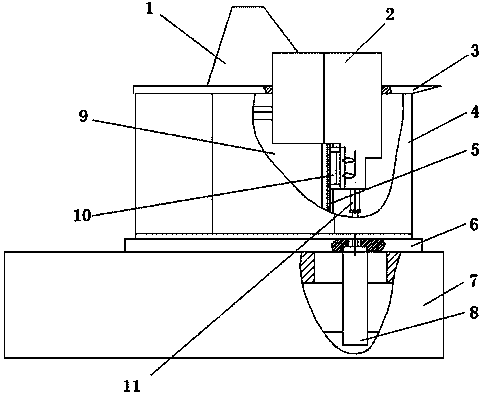
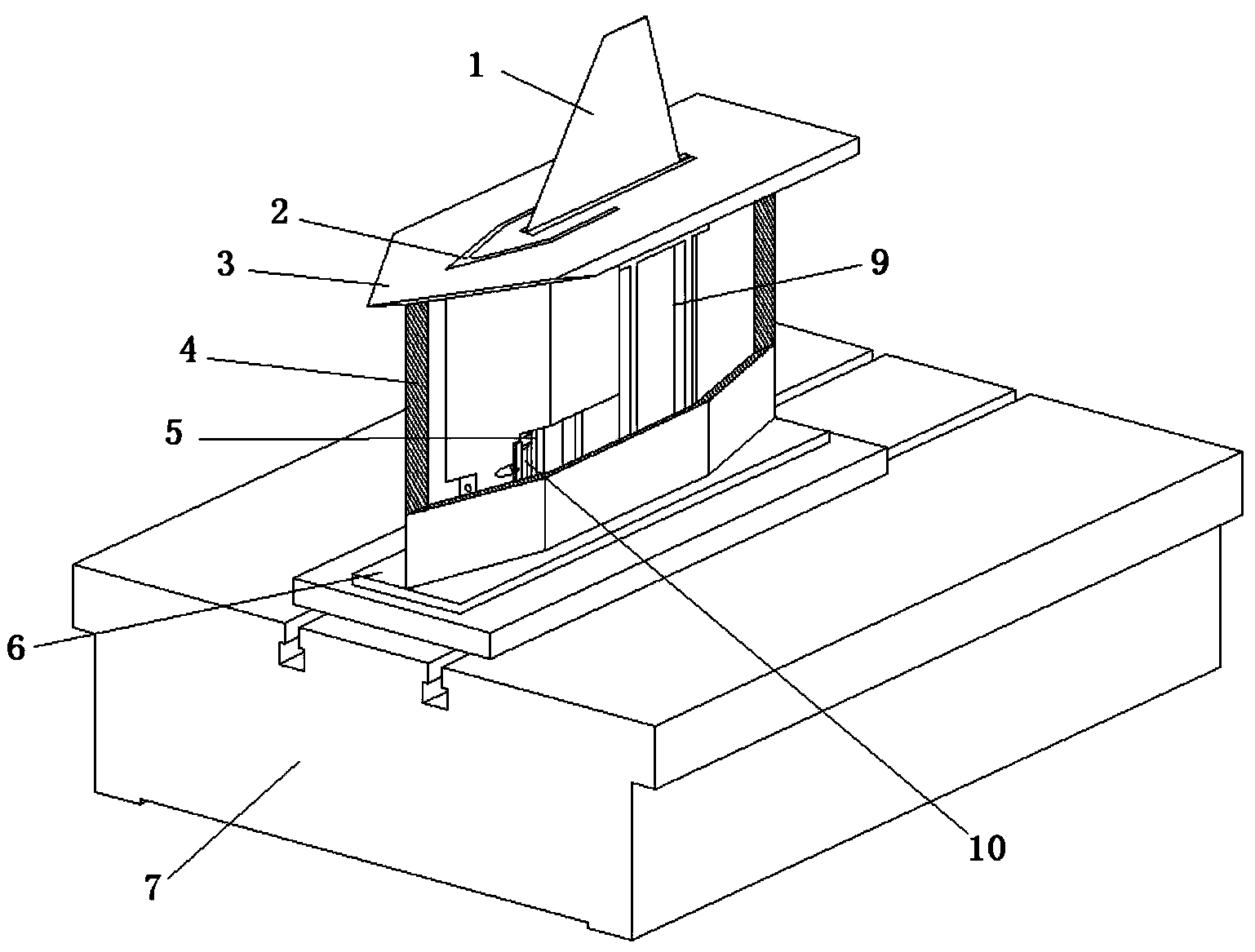
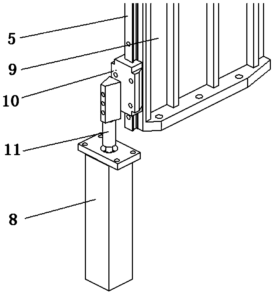
[0026] figure 1 It is a schematic diagram of the aeroelastic test device for rudder airfoil in a high-speed wind tunnel. In the figure 1 is a model (rudder surface model or airfoil model), 2 is a "V" protective cover, 3 is a reflector, 4 is a support baffle, 5 is a Guide rail, 6 is a base, 7 is a bottom platform, 8 is a cylinder, 9 is a model support, 10 is a guide rail slider, and 11 is a cylinder joint.

[0027] Such as figure 1 , 2 As shown, the model 1 (for the rudder surface model or the airfoil model) is installed on the model support 9, and the rudder shaft support form of the rudder surface model 1 or the airfoil model 1 is realized by installing different clamps on the model support 9. The form of root support is described below by taking the rudder surface model as an example.

[0028] The rudder surface model 1 is not connected with the reflector 3 and there is a suitable gap between the reflector 3 and the reflector 3 . The reflector 3 provides the root flow fi...


PUM


Abstract

The invention provides a fin and wing aeroelasticity test device of a high-speed wind tunnel. The fin and wing aeroelasticity test device of the high-speed wind tunnel comprises a protection mechanism, a supporting mechanism, a reflection board, a supporting baffle, a base and a bottom surface platform. The protection mechanism is arranged in front of the supporting mechanism and mainly comprises a protection cover, a guide rail and a cylinder. The cylinder is fixed to the lower portion of the base. The base is installed on the bottom surface platform, and the position of the base can be adjusted front and back. The protection cover is connected with the cylinder and the guide rail in a mode of moving vertically. The supporting mechanism is fixed to the base and used for supporting a model. The reflection board is arranged at the root of the model through the supporting baffle. The reflection board is provided with an opening matched with the protection cover and the model so that the reflection board cannot make contact with the protection cover or the model. The fin and wing aeroelasticity test device of the high-speed wind tunnel can be used for carrying out fin and wing aeroelasticity test research in the high-speed wind tunnel. The protection mechanism is used for protecting the model against impact from a wind tunnel flow field, and when the vibration amplitude of the model is large, vibration damage to the model can be prevented.

Description

technical field [0001] The invention relates to a high-speed wind tunnel rudder wing surface aeroelastic test device for performing aeroelasticity tests on the rudder surface and the wing surface in the high-speed wind tunnel. Background technique [0002] During the design of the aircraft, it is necessary to avoid flutter within its flight envelope. For this kind of problem, wind tunnel test is an indispensable research method. Through the wind tunnel test, the evaluation of aeroelastic characteristics such as aerodynamic shape and structural design can be completed, and the flutter boundary of the aircraft and its components can be determined. [0003] At present, aeroelasticity tests in low-speed and sub-transonic wind tunnels are mainly carried out in China, while aeroelasticity tests in supersonic wind tunnels are rarely carried out, and aeroelasticity test devices for hypersonic wind tunnels have not yet been developed. The main difficulties in the design of the test...

Claims


Application Information

Patent Timeline
Patent Type & Authority Applications(China)
IPC IPC(8): G01M9/02
Inventor 季辰赵玲侯英昱付天厚刘子强李锋
Owner CHINA ACAD OF AEROSPACE AERODYNAMICS
Why Eureka
Try Eureka