Measurement Method of Modulation Coefficient of Electro-optic Phase Modulator

An electro-optic phase modulation and modulation coefficient technology, applied in the field of optoelectronics, can solve the problem of separate calibration of the frequency response of the photodetector, avoid the influence of the response of the photodetector, realize the self-calibration measurement, and improve the stability.

Active Publication Date: 2017-01-18
UNIV OF ELECTRONICS SCI & TECH OF CHINA
View PDF7 Cites 0 Cited by
  • Summary
  • Abstract
  • Description
  • Claims
  • Application Information

AI Technical Summary

Problems solved by technology

[0004] Aiming at the problem that the frequency response of the photodetector needs to be calibrated separately in the electrical domain measurement method of the modulation coefficient of the electro-optical phase modulator, the purpose of the present invention is to provide a measurement method for the modulation coefficient of the electro-optic phase modulator, and realize a self-calibrating electro-optic phase modulator High-resolution, high-accuracy electrical domain measurement method for modulation factor

Method used


Image

  • Measurement Method of Modulation Coefficient of Electro-optic Phase Modulator
  • Measurement Method of Modulation Coefficient of Electro-optic Phase Modulator
  • Measurement Method of Modulation Coefficient of Electro-optic Phase Modulator

Examples


Embodiment 1

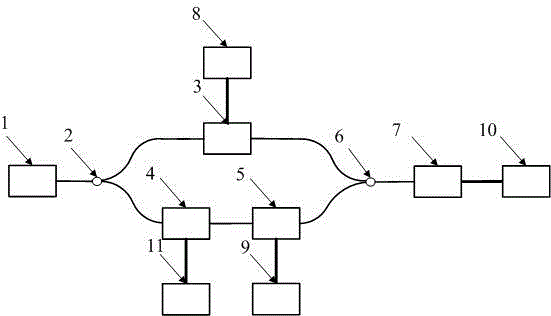
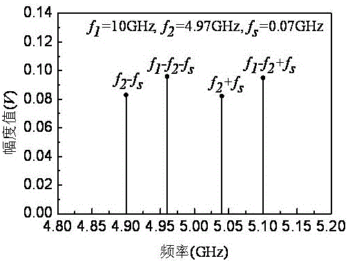
[0063] Set the output wavelength of laser 1 to λ 0 =1553.60nm (corresponding frequency f 0 =193.1THz), taking one of the measurement frequency points as an example, the frequency f of the sinusoidal signal output by the first signal source 8 1 =10GHz, the sinusoidal signal frequency f of the second microwave signal source 9 output 2 =4.97GHz, the sinusoidal signal frequency f of the third signal source 11 output s =0.07GHz, the frequency in the signal of the output signal of the optical fiber interferometer under the action of the above three sinusoidal signals by the sampling circuit 10 is 4.96GHz (f 1 -f 2 -f s ), 5.1GHz (f 1 -f 2 +f s ), 4.9GHz (f 2 -f s ), 5.04GHz (f 2 +f s ) magnitude, respectively denoted as i(f 1 -f 2 +f s ), i(f 1 -f 2 -f s ), i(f 2 +f s ), i(f 2 -f s ); figure 2 In this embodiment, the method for measuring the modulation coefficient of the electro-optic phase modulator of the present invention is used to obtain the amplitude val...

Embodiment 2

[0069] Set the output wavelength of laser 1 to λ 0 =1551.19nm (corresponding frequency f 0 =193.4THz), taking one of the measurement frequency points as an example, the frequency f of the sinusoidal signal output by the first signal source 8 1 =20GHz, the sinusoidal signal frequency f of the second microwave signal source 9 output 2 =9.9GHz, the sinusoidal signal frequency f of the third signal source 11 output s =0.08GHz, the frequency in the signal of the output signal of the optical fiber interferometer under the effect of the above three sinusoidal signals by sampling circuit 10 is 9.82GHz (f 2 -f s ), 9.98GHz (f 2 +f s ), 10.02GHz (f 1 -f 2 -f s ), 10.18GHz (f 1 -f 2 +f s ) magnitude, respectively denoted as i(f 2 -f s ), i(f 2 +f s ), i(f 1 -f 2 -f s ), i(f 1 -f 2 +f s ); Figure 4 In this embodiment, the method for measuring the modulation coefficient of the electro-optic phase modulator of the present invention is used to obtain the amplitude valu...

Embodiment 3

[0075] Set the output wavelength of laser 1 to λ 0 =1550.55nm (corresponding frequency f 0 =193.48THz), taking one of the measurement frequency points as an example, set the frequency f of the sinusoidal signal output by the first signal source 8 1 =15GHz, the sinusoidal signal frequency f of the second microwave signal source 9 output 2 =7.46GHz, the sinusoidal signal frequency f of the third signal source 11 output s =0.1GHz, the frequency in the signal of the output signal of the optical fiber interferometer under the action of the above three kinds of sinusoidal signals by the sampling circuit 10 is 7.44GHz (f 1 -f 2 -f s ), 7.64GHz (f 1 -f 2 +f s ), 7.36GHz (f 2 -f s ), 7.56GHz (f 2 +f s ) magnitude, respectively denoted as i(f 1 -f 2 +f s ), i(f 1 -f 2 -f s ), i(f 2 +f s ), i(f 2 -f s ); Image 6 In this embodiment, the method for measuring the modulation coefficient of the electro-optic phase modulator of the present invention is used to obtain the...


PUM


Abstract

The invention discloses a method for measuring the modulation coefficient of an electro-optical phase modulator, and relates to the field of optoelectronic technology. The invention aims to solve the problem that the phase modulation signal cannot be directly detected on a photodetector and the non-linearity in the conversion between PM-IM and FM-IM cannot be avoided The problem of the process, the present invention adopts the optical fiber interferometer as the measuring device, the optical fiber interferometer is composed of a beam splitter, an electro-optic phase modulator to be tested, an acousto-optic frequency shifter, an auxiliary electro-optic phase modulator and a beam combiner, wherein the electro-optic phase to be measured The modulator is placed on one interference arm of the fiber optic interferometer, the acousto-optic frequency shifter and the auxiliary electro-optic phase modulator are placed on the other interference arm; the three devices are respectively loaded with sinusoidal signals of different frequencies; The frequency relationship of the sinusoidal signal eliminates the frequency response of the photodetector, realizes the self-calibration measurement, and improves the accuracy of measuring the modulation coefficient of the electro-optic phase modulator, which has good application value.

Description

technical field [0001] The invention relates to the field of optoelectronic technology, and more specifically designs an electro-optic phase modulator modulation coefficient that solves the problem that the phase modulation signal cannot be directly detected on the photodetector and avoids the nonlinear process in the conversion of PM-IM and FM-IM measurement method. Background technique [0002] The electro-optic phase modulator is one of the key devices in the optical fiber communication system. The electro-optical phase modulator has the advantages of no bias and linear modulation. It is used in high-speed optical fiber communication and coherent optical communication systems, especially the optical play an integral role in signal generation. The modulation coefficient of the electro-optic phase modulator is one of the important characteristic parameters of the electro-optic phase modulator, which reflects the modulation efficiency of the electro-optic phase modulator, a...

Claims


Application Information

Patent Timeline
Patent Type & Authority Patents(China)
IPC IPC(8): G01M11/02
Inventor 张尚剑王恒邹新海尹欢欢张雅丽刘永
Owner UNIV OF ELECTRONICS SCI & TECH OF CHINA
Why Eureka
Try Eureka