Light guiding plate, backlight module and display device

A technology of backlight module and light guide plate, which is applied in lighting devices, fixed lighting devices, optics and other directions to achieve the effects of reducing distance, excellent optical performance and high brightness

Active Publication Date: 2014-07-16
SHANGHAI TIANMA MICRO ELECTRONICS CO LTD +1
View PDF13 Cites 13 Cited by
  • Summary
  • Abstract
  • Description
  • Claims
  • Application Information

AI Technical Summary

Problems solved by technology

However, since α is a certain value, the light incident structure of the light guide plate limits the development of low cost, low power consumption and miniaturization of the backlight module to a certain extent.

Method used


Image

  • Light guiding plate, backlight module and display device
  • Light guiding plate, backlight module and display device
  • Light guiding plate, backlight module and display device

Examples


Embodiment 1

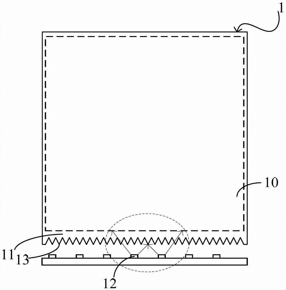
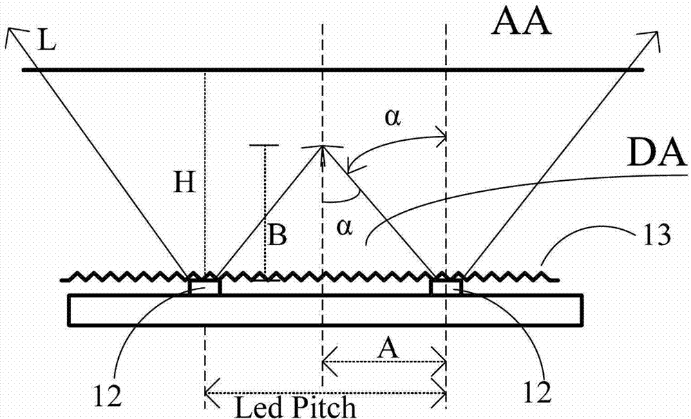
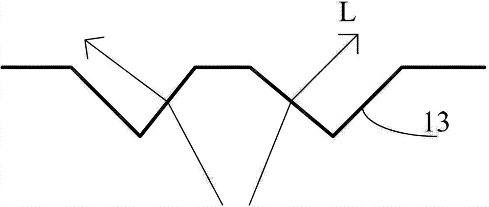
[0032] like Figure 2a , Figure 2b As shown, the present invention discloses a structure of a light guide plate, the light guide plate is in the shape of a flat plate, and is used in a side backlight module. The light guide plate 1 mainly includes a light incident surface 11, the light incident surface 11 is made of the same dielectric material polycarbonate, a light exit surface 10 connected to the light incident surface 11, and two concave recesses are arranged on the light incident surface 11. The sawtooth structures on the light-incoming surface are respectively the first sawtooth structure 14 and the second sawtooth structure 15, and the two sawtooth structures are perpendicular to the light-emitting surface 10. Each unit structure of the sawtooth structure is a continuous structure with equal intervals. The shape is triangular. The sawtooth structure is set on the light incident surface by mechanical overmolding. Specifically, the first sawtooth structure 14 is provi...

Embodiment 2

[0039] On the basis of the first embodiment disclosed in the present invention, the present invention discloses another structure of the light guide plate, such as Figure 3a , Figure 3b As shown, it is a schematic diagram of the light guide plate. The light guide plate is flat and used in the side backlight module. The light guide plate 1 mainly includes a light incident surface 11, the light incident surface 11 is made of two media with different refractive indices, the medium at the front end of the light incident surface is polycarbonate M1, and the medium of other parts of the light incident surface is polymethacrylic acid Methyl ester M2. The light-emitting surface 10 connected to the light-incident surface 11 and the light-incident surface 11 are provided with two sawtooth structures recessed into the light-incidence surface, which are respectively the first sawtooth structure 14 and the second sawtooth structure 15, and the two sawtooth structures are vertical On th...


PUM


Abstract

The invention discloses a light guiding plate and a backlight module adopting the light guiding plate. The light guiding plate comprises a light incidence face and a light emergence face connected with the light incidence face, wherein the light incidence face is provided with two or more sawtooth structures embedded into the light incidence face, and the sawtooth structures are perpendicular to the light emergence face. The light guiding plate has the advantages of being even in emergent light, light in brightness, excellent in optical performance and the like.

Description

technical field [0001] The invention relates to a light guide plate and a backlight module thereof, in particular to a light guide plate with uniform light output, high brightness and excellent optical performance and a backlight module using the light guide plate. Background technique [0002] The existing backlight module includes a light source and a light guide plate. The light source is arranged relative to the light incident surface of the light guide plate. The light guide plate guides the propagation direction of the light beam emitted by the light source, and converts the point light source or line light source into a surface light source to emit. For the light guide plate with LED (light emitting diode) side backlight, at present, a sawtooth structure is generally adopted on the light incident surface of the light guide plate relative to the light source. like Figure 1a As shown, the light guide plate 1 is composed of a light incident surface 11 and a light exit s...

Claims


Application Information

Patent Timeline
Patent Type & Authority Applications(China)
IPC IPC(8): G02B6/00F21V8/00F21S8/00F21Y101/02
Inventor 周锡仁
Owner SHANGHAI TIANMA MICRO ELECTRONICS CO LTD
Why Eureka
Try Eureka