All-dimensional exhibition device for spatial model demonstrations
A technology of three-dimensional models and display devices, applied in teaching models, educational tools, instruments, etc., can solve the problems of time occupation, difficult adjustment of camera height, and inconvenient teaching for teachers, and achieve convenient storage, convenient observation, and strong portability Effect
- Summary
- Abstract
- Description
- Claims
- Application Information
AI Technical Summary
Problems solved by technology
Method used
Image

Examples
Embodiment
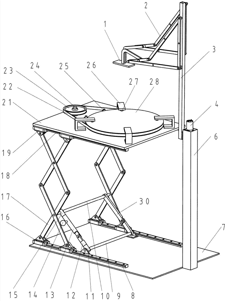
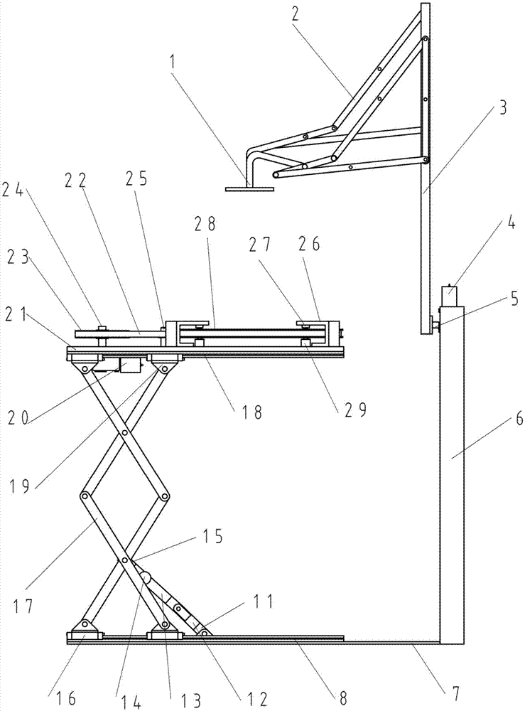
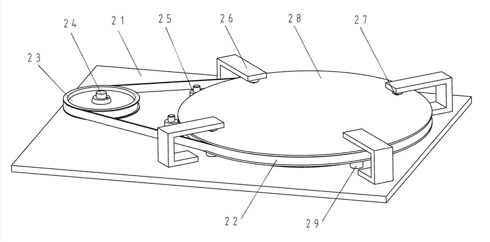
[0021] The present invention comprises a base 7, a scissor lifting frame 17, an object stage and a video camera, and two parallel lower linear guide rails 8 are fixed to the base 7. The bottom fulcrum of the scissor lift frame 17 is connected with the lower linear guide rail 8 through the lower slider 16, and the top fulcrum is connected with the upper linear guide rail 18 through the upper slider 19; Below the panel 21; the two ends of the upper cross bar 10 of the self-locking mechanism are hinged with the first middle hinge point of the scissor lift frame 17, and the lower cross bar 9 is hinged with the hinge seat located on the base 7;
[0022] Described self-locking mechanism is a space metamorphosis mechanism, comprises upper cross bar 10, lower cross bar 9 and two connecting rod pairs and forms, and one of them is common connecting rod pair 30, and its two ends are respectively connected with upper cross bar 10 and The lower cross bar 9 is hinged. Another self-locking ...
PUM
 Abstract
Description
Claims
Application Information
 - Generate Ideas
- Intellectual Property
- Life Sciences
- Materials
- Tech Scout
- Unparalleled Data Quality
- Higher Quality Content
- 60% Fewer Hallucinations
Browse by: Latest US Patents, China's latest patents, Technical Efficacy Thesaurus, Application Domain, Technology Topic, Popular Technical Reports.
© 2025 PatSnap. All rights reserved.Legal|Privacy policy|Modern Slavery Act Transparency Statement|Sitemap|About US| Contact US: help@patsnap.com