
Spliced wall color correction method and system

A color correction and color technology, applied to cathode ray tube indicators, instruments, static indicators, etc., can solve the problems of expensive color measurement equipment, increased adjustment time, and no consideration, so as to improve adaptability and speed up The adjustment process and the effect of fast correction speed

Inactive Publication Date: 2014-07-16
GUANGDONG VTRON TECH CO LTD
View PDF6 Cites 3 Cited by
  • Summary
  • Abstract
  • Description
  • Claims
  • Application Information

AI Technical Summary

Problems solved by technology

This method takes a short time to adjust, but it does not take into account the defects of the images captured by the camera. When the camera captures a screen with a light source, the fatal defect of the image is that the center of the captured area is the brightest, and the brightness decreases from the circle to the edge. , which causes a very large error when adjusting the screen color, and at the same time increases the adjustment time
[0004] Another correction method is to use each projection channel to project the red, green, and blue colors from 0-255 256 times, collect and establish mapping data respectively, and then calculate the public intersection of the colors, and then repeatedly correct the individual corrections on this basis. The system modifies the input image, then inputs it to the projector and measures the color data until the number of acquisitions of the corrected mapping data and the target color mapping data is 3*256=768 times. This correction process may require multiple iterations. As the number increases, the time spent also doubles
In addition, the system requires color measurement equipment to complete the calibration function. The use of professional color measurement equipment is expensive, the operation is complicated, and the versatility of each manufacturer is not good, and some other general-purpose camera equipment have performed color processing on the original image. Larger color distortion

Method used


Image

  • Spliced wall color correction method and system
  • Spliced wall color correction method and system
  • Spliced wall color correction method and system

Examples


Embodiment 1

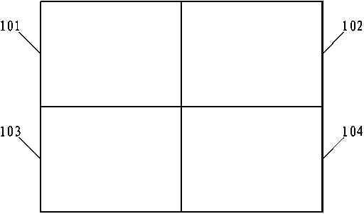
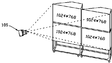
[0033] Such as figure 1 As shown, it is a flowchart of a specific embodiment of a video wall color correction method according to the present invention. In this specific embodiment, the video wall is formed by splicing several display units, for example, as figure 2 As shown, the video wall screen is a 2×2 video wall display unit, 101, 102, 103, and 104 represent four display units respectively, and cameras are installed on the video wall, as shown in image 3 As shown, the camera 105 is generally placed directly in front of the entire video wall screen, and its shooting range covers the entire video wall. It is generally composed of photosensitive devices, optical filters, optical lenses, etc., and is used to take pictures of the video wall for computer reading and analysis. see figure 1 , the specific steps of a method for correcting the color of a video wall in this specific embodiment include:

[0034] Step S1. Set each display unit to display a picture, and the colors...


PUM


Abstract

The invention relates to the field of display screen color correction, in particular to a spliced wall color correction method and system. The method includes the steps that it is set that each display unit displays one picture, and each color, capable of being displayed on a screen system, in the picture corresponds to one color region; a picture covering a whole spliced wall is taken; the color mean value of color regions of all the display units is extracted according to the taken picture; a reference display unit is selected; the color mean value of the color regions in all the display units is adjusted to be the color mean value of each color region in the reference display unit. Each color is adjusted according to the mean value of the color, the color of each display unit is adjusted to be the color of a reference screen, and self-adaptability of color correction is greatly improved; by selecting one display unit as a reference unit to carry out adjustment, in the color correction process, switching of primary colors in the display units is not needed, the adjustment process is greatly accelerated because the colors are well set at a time, and the correction time is short.

Description

technical field [0001] The present invention relates to the field of color correction of display screens, and more specifically, to a method and system for color correction of a video wall. Background technique [0002] With the improvement of people's demand for display information transmission, the application fields of large-screen display have spread to various fields such as public display, transportation dispatching and commanding, weather monitoring, power and telecommunications monitoring, fire monitoring and commanding, and military commanding. Although the demand for large-screen display applications is increasing, the consistent correction of color and brightness of the multi-screen video wall system has become a major problem for system integrators. [0003] An existing multi-screen wall correction method is to use a camera to capture the pre-set colors of each screen, and then extract the color information of each display unit from the captured pictures, and per...

Claims


Application Information

Patent Timeline
IPC IPC(8): G09G5/14
Inventor 刘雄伟
Owner GUANGDONG VTRON TECH CO LTD
Learn More