Formation method of double metal gate structure and cmos transistor
A dual-metal gate and transistor technology, applied in the direction of transistors, electric solid-state devices, semiconductor devices, etc., can solve the problems of excessive gate leakage current and difficulty in ensuring device performance, so as to reduce the possibility, ensure the thickness, and simplify the Effect of the etch step
Active Publication Date: 2016-08-31
SEMICON MFG INT (SHANGHAI) CORP
View PDF10 Cites 0 Cited by
- Summary
- Abstract
- Description
- Claims
- Application Information
AI Technical Summary
Problems solved by technology
However, in actual production, it is found that even if a similar etch stop layer is used, it is still difficult to guarantee the performance of the device, for example, the defect of excessive gate leakage current often occurs
Method used
View moreImage
Smart ImageViewing Examples
Examples
Embodiment
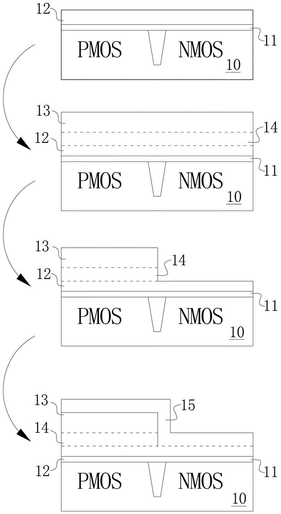
[0076] Embodiment: A double metal gate structure including an oxide layer of an etching stopper layer is prepared by adopting the above-mentioned "formation process of a double metal gate structure".
Login to View More PUM
| Property | Measurement | Unit |
|---|---|---|
| thickness | aaaaa | aaaaa |
| thickness | aaaaa | aaaaa |
| thickness | aaaaa | aaaaa |
Abstract
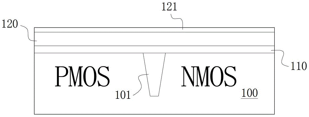
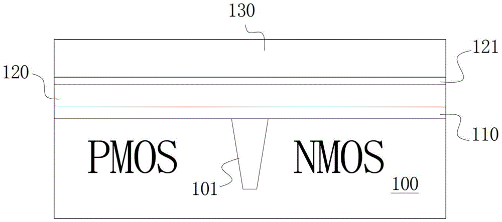
The invention provides a forming method of a double-metal grid structure, and a CMOS transistor. After an etching barrier layer on a semiconductor substrate is formed, an oxide layer of the etching barrier layer is formed on the surface of the etching barrier layer, and then a first metal layer is deposited. The oxide layer of the etching barrier layer can effectively prevent mutual effects such as atom diffusion and the like between the first metal layer and the etching barrier layer, it is ensured that the portion of the first metal layer disposed at a second area can be depleted without taking an over-etching mode, at the time when an etching step is simplified, the thickness of the etching barrier layer can be ensured in subsequently formed PMOS and NMOS metal gates, the possibility that metal gate ions filter into a high-K dielectric layer and even a transistor FET area of the substrate is reduced, and the electrical performance of an integrated circuit is guaranteed.
Description
technical field [0001] The invention relates to the technical field of semiconductor manufacturing, in particular to a method for forming a double-metal gate structure applied in a CMOS transistor and a CMOS transistor formed by the method. Background technique [0002] With the rapid development of integrated circuit (abbreviated as IC) manufacturing technology, especially after entering the field of submicron feature size, the size of traditional integrated circuits continues to shrink, while the channel length and gate oxide (generally SiO2) in MOS transistors 2 ) thickness is scaled down, exacerbating defects such as polysilicon loss, high gate resistance, and dopant (such as boron) penetrating into the channel region of the device, causing increased gate leakage current and other defects. For this reason some high K (dielectric constant) dielectric materials replace traditional SiO 2 It can effectively reduce gate leakage, but polysilicon is not compatible with high-K ...
Claims
Login to View More Application Information
Patent Timeline
 Patent Type & Authority Patents(China)
IPC IPC(8): H01L21/28H01L27/092H01L29/423
CPCH01L27/0928H01L29/4238
Inventor 陈勇
Owner SEMICON MFG INT (SHANGHAI) CORP
- R&D Engineer
- R&D Manager
- IP Professional
- Industry Leading Data Capabilities
- Powerful AI technology
- Patent DNA Extraction
Learn More Browse by: Latest US Patents, China's latest patents, Technical Efficacy Thesaurus, Application Domain, Technology Topic, Popular Technical Reports.
© 2024 PatSnap. All rights reserved.Legal|Privacy policy|Modern Slavery Act Transparency Statement|Sitemap|About US| Contact US: help@patsnap.com


