Graphite rod slicing and graphite gasket processing equipment

A graphite rod and graphite pad technology, which is applied in the field of graphite rod slicing processing graphite gasket equipment, can solve problems such as easy to produce defective products, low work efficiency, and difficulty for workers to control the thickness of graphite sheets

Active Publication Date: 2020-10-27
内蒙古骅扬高新材料科技有限公司
View PDF8 Cites 18 Cited by
  • Summary
  • Abstract
  • Description
  • Claims
  • Application Information

AI Technical Summary

Problems solved by technology

[0005] In order to overcome the disadvantages that workers manually cut and punch graphite rods, the work efficiency is low, and it is difficult for workers to control the thickness of graphite sheets, which easily produces defective products. The thickness of the sheet, to avoid defective graphite rod slice processing graphite gasket equipment

Method used


Image

  • Graphite rod slicing and graphite gasket processing equipment
  • Graphite rod slicing and graphite gasket processing equipment
  • Graphite rod slicing and graphite gasket processing equipment

Examples


Embodiment 1

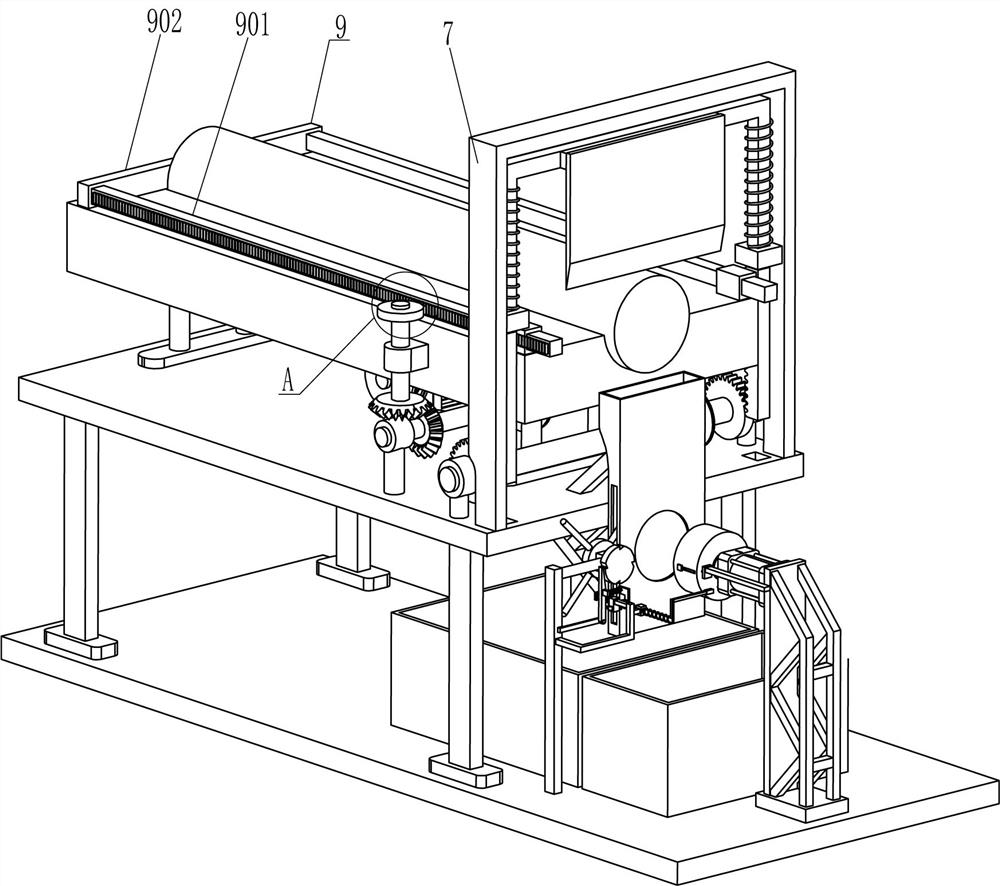
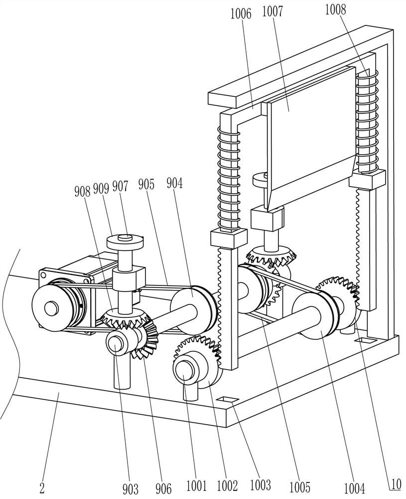
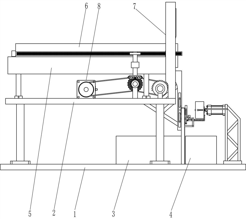
[0026] A graphite rod slice processing graphite gasket equipment, see Figure 1-7 , including a bottom plate 1, a stage 2, a first collection frame 3, a second collection frame 4, a placement plate 5, an N-shaped frame 7, a servo motor 8, a pusher assembly 9, a cutting assembly 10, a blanking assembly 11 and Stamping assembly 12, the top of the bottom plate 1 is installed with the stage 2 through bolts, the first collection frame 3 and the second collection frame 4 are placed on the bottom plate 1, the first collection frame 3 is located on the left side of the second collection frame 4, and the object stage 2 The top is equipped with a placing plate 5, an N-shaped frame 7 and a servo motor 8 through bolts. The servo motor 8 is located under the placing plate 5. The pushing assembly 9 and the cutting assembly 10 are installed on the placing plate 5. The bottom plate 1 is equipped with a blanking Assembly 11 and stamping assembly 12.

[0027] The pushing assembly 9 includes a ...

Embodiment 2

[0037] On the basis of Example 1, see Figure 5 , Figure 7 and Figure 8 , also includes a second slider 13, a slide bar 14, a contact bar 15, a fourth spring 16, a fifth spring 17, a contact frame 18, a sixth spring 19 and a fixed bar 20, and the second support bar 1105 is slidably arranged There is a second slider 13, a fourth spring 16 is sleeved on the second support rod 1105, one end of the fourth spring 16 is connected with the second slider 13, the other end of the fourth spring 16 is connected with the second support rod 1105, and the second There is a guide hole on the second slide block 13, and the slide bar 14 is slidably arranged in the guide hole. The rear side of the clamp bar 1106 is connected with the contact bar 15, and the slide bar 14 is covered with the fifth spring 17. One end is connected with the second slide block 13, the other end of the fifth spring 17 is connected with the slide bar 14, the rear side of the second support bar 1105 is provided with...


PUM


Abstract

The invention relates to the field of graphite sheet processing, in particular to graphite rod slicing and graphite gasket processing equipment. The graphite rod slicing and graphite gasket processingequipment is high in working efficiency, can control the thickness of graphite sheets, and avoids defective products. According to the technical scheme, the graphite rod slicing and graphite gasket processing equipment comprises a bottom plate and a first collecting frame, wherein an objective table is bolted on the bottom plate; and the first collecting frame and a second collecting frame are placed on the bottom plate. According to the graphite rod slicing and graphite gasket processing equipment, a graphite rod can be cut through a cutting assembly, a stamping assembly can stamp the cut graphite sheets, so that cutting and stamping are carried out at the same time, and therefore the working efficiency can be improved; and the graphite rod is conveyed by a machine instead of manual work, so that the thickness of the graphite sheets can be effectively guaranteed.

Description

technical field [0001] The invention relates to the field of graphite sheet processing, in particular to a graphite rod slice processing graphite gasket equipment. Background technique [0002] Graphite rod is a non-metallic product, which is made of carbon, graphite and appropriate adhesive, which is formed by extrusion, baked at 2200 degrees and then coated with a layer of copper. It is resistant to high temperature, has good conductivity, and is not easy to break. It is suitable for It is used to cut metal into required shapes, and is often used to make graphite sheets. When making graphite sheets, graphite rods need to be cut. [0003] Now generally, the worker manually moves the graphite rod to make the cutting tool cut the graphite rod. After cutting, the worker puts the cut graphite sheet on the processing table, and then punches the cut graphite sheet with a ring cutter to form Graphite gasket, this method is inefficient, and it is difficult for workers to control t...

Claims


Application Information

Patent Timeline
Patent Type & Authority Applications(China)
IPC IPC(8): B28D1/22B28D1/00B28D7/00
CPCB28D1/22B28D1/00B28D7/00
Inventor 张少东
Owner 内蒙古骅扬高新材料科技有限公司
Why Eureka
Try Eureka