Propulsion bay

A propulsion device and space propulsion technology, which is applied to the propulsion system device of space navigation vehicle, the guidance device of space navigation vehicle, the docking device of space navigation vehicle, etc., can solve the problems of insufficiency and low flexibility, and achieve low thrust and increase payload. , the effect of good performance

Active Publication Date: 2014-07-16
CENT NAT DETUD SPATIALES C N E S
View PDF7 Cites 7 Cited by
  • Summary
  • Abstract
  • Description
  • Claims
  • Application Information

AI Technical Summary

Problems solved by technology

[0010] However, the aforementioned known techniques have disadvantages
[0011] stage 23 engine 230 is a liquid propelled engine with little flexibility in its use (any operational interruption is guaranteed)

Method used


Image

  • Propulsion bay
  • Propulsion bay
  • Propulsion bay

Examples


Embodiment Construction

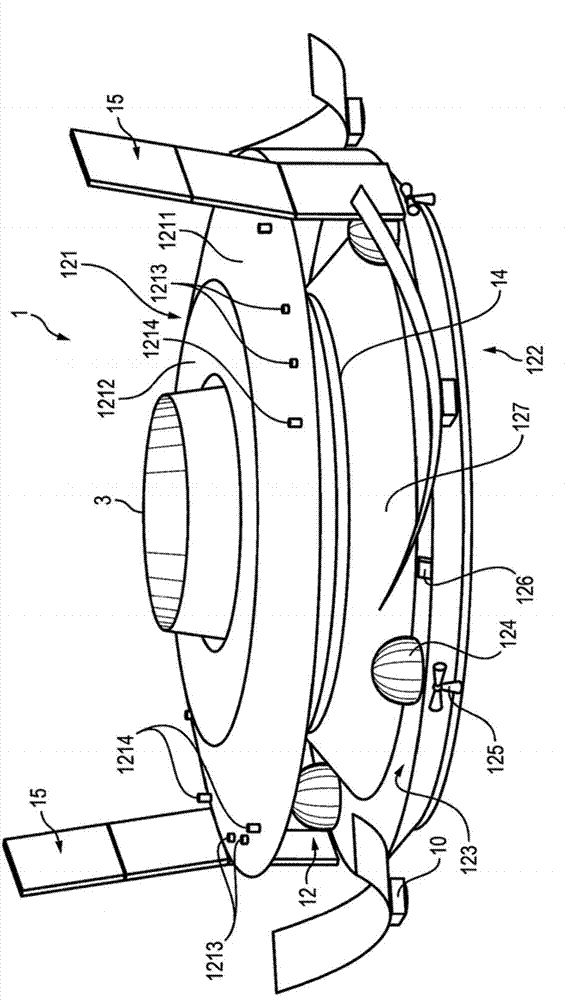
[0044] Figures 3 to 14 A possible embodiment of the propulsion nacelle 1 according to the invention is shown schematically.

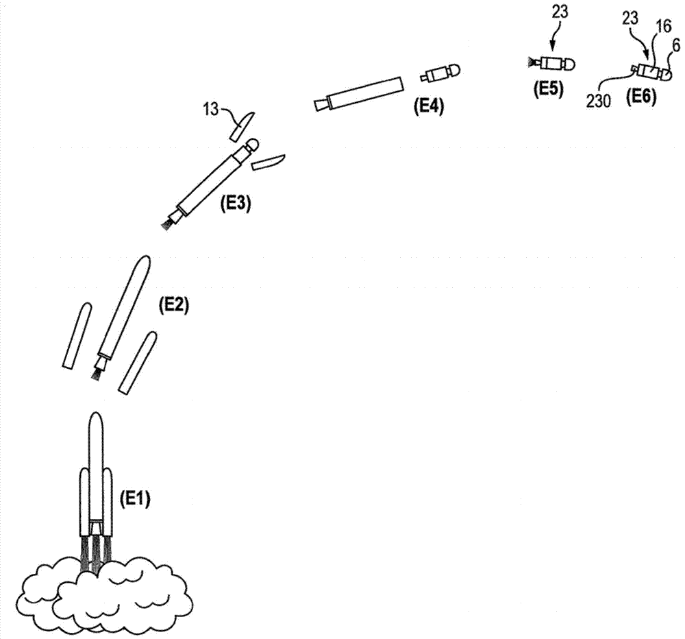
[0045] Said capsule 1 is intended to be accommodated in a launch vehicle 2 .

[0046] Compared to the launch vehicle 2 described with reference to the background art, the capsule 1 is additionally and at least temporarily accommodated in the launch vehicle 2 at the level of the equipment compartment 16 . No changes are required to launch vehicle 2 to accommodate module 1 . The dimensions of the capsule 1 are thus adapted for accommodation inside the launch vehicle 2 : typically a few meters in diameter and about a meter in height. Apart from this difference, the launch vehicle 2 transporting the capsule 1 at least temporarily corresponds to the introduction given in the background section of the present application and will not be described further for reasons of clarity and brevity.

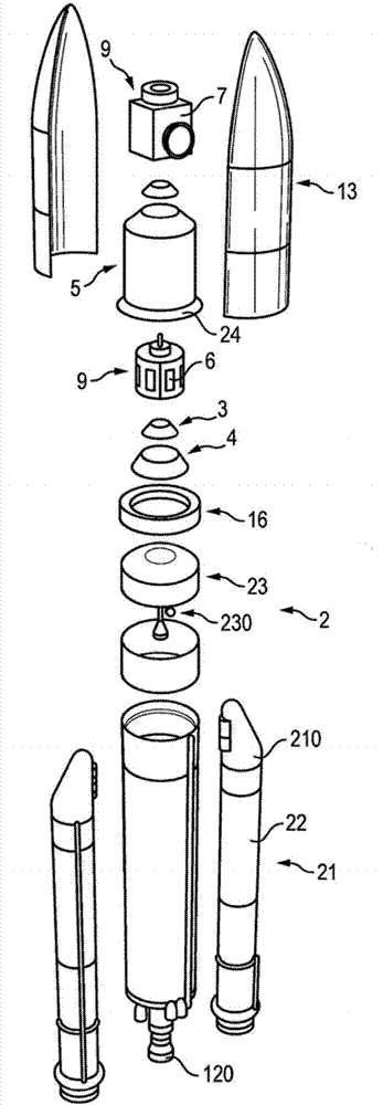
[0047] Such as image 3 and 4 As shown, the module 1 is of sub...


PUM


Abstract

The invention relates to a propulsion bay (1) intended to be transported, at least temporarily, in a space launch vehicle (2) and comprising an adapter (3) that co-operates with at least one system located, at least temporarily, on board the bay (1), said system comprising an electrical power supply. The bay is characterized in that it also comprises at least one electric space propulsion engine that can be powered by the power supply of the system.

Description

technical field [0001] The invention relates to a propulsion module intended to be transported at least temporarily in a space launch vehicle, said propulsion module comprising an adapter cooperating with at least temporarily loaded at least one system comprising a power source. Background technique [0002] Such as figure 1 As shown, a space launch vehicle 2 is known for at least temporarily transporting at least one equipment module 16 to which equipment 6 or 7 and propulsion means 230 are fastened. [0003] Said equipment bay 16 comprises adapters 3 , 4 cooperating with at least a system 6 at least temporarily loaded on the bay 16 . The onboard system 6 usually forms a satellite. [0004] In order to send the system 6 into space and put it into orbit, the launch vehicle 2 conventionally comprises several stages, namely: [0005] - lift-off stage 21 comprising a booster 210 propelled with known solid fuels; [0006] - a lower cryogenic fuel stage 22 comprising an engin...

Claims


Application Information

Patent Timeline
Patent Type & Authority Applications(China)
IPC IPC(8): B64G1/00B64G1/64B64G1/40B64G1/24B64G1/42B64G1/44B64G1/50
CPCB64G1/405B64G1/242B64G1/422B64G1/428B64G1/44B64G1/503B64G1/641B64G1/40B64G1/2427B64G1/415B64G1/42B64G1/443B64G1/64
Inventor P·比尔泰尔
Owner CENT NAT DETUD SPATIALES C N E S
Why Eureka
Try Eureka