
Power conversion device

A technology of power conversion device and power module, which is applied in the direction of converting irreversible DC power input into AC power output, support structure installation, cooling/ventilation/heating renovation, etc.

Inactive Publication Date: 2014-07-16
FUJI ELECTRIC CO LTD
View PDF17 Cites 8 Cited by
  • Summary
  • Abstract
  • Description
  • Claims
  • Application Information

AI Technical Summary

Problems solved by technology

Therefore, there is an unsolved problem that, since the case is used as a part of the heat conduction path, the case is also required to have good thermal conductivity, so that the material is limited to a metal with high thermal conductivity, so when miniaturization and light weight are required. Lightweight materials such as resins cannot be selected for lightweight power conversion devices, making it difficult to achieve weight reduction

Method used


Image

  • Power conversion device
  • Power conversion device
  • Power conversion device

Examples


Embodiment approach 6

[0158] According to Embodiment 6, the control circuit board 22 and the power circuit board 23 on which the heating circuit components are mounted are supported by the heat conduction support plate portions 62 a and 65 a via the heat conduction members 61 and 64 , respectively, and these heat conduction support plate portions 62 a and 65 a pass through the heat conduction support plate portions 62 a and 65 a. The support side plate portions 62c and 65c are connected to the heat sink 3 . As a result, the heat generated by the heating circuit components mounted on the control circuit board 22 is conducted to the heat conduction support plate portion 62 a through the heat conduction member 61 , and is conducted from the heat conduction support plate portion 62 a to the cooling body 3 via the heat conduction support side plate portion 62 c. To dissipate heat.

[0159] Similarly, the heat generated by the heating circuit components mounted on the power circuit board 23 is conducted ...


PUM


Abstract

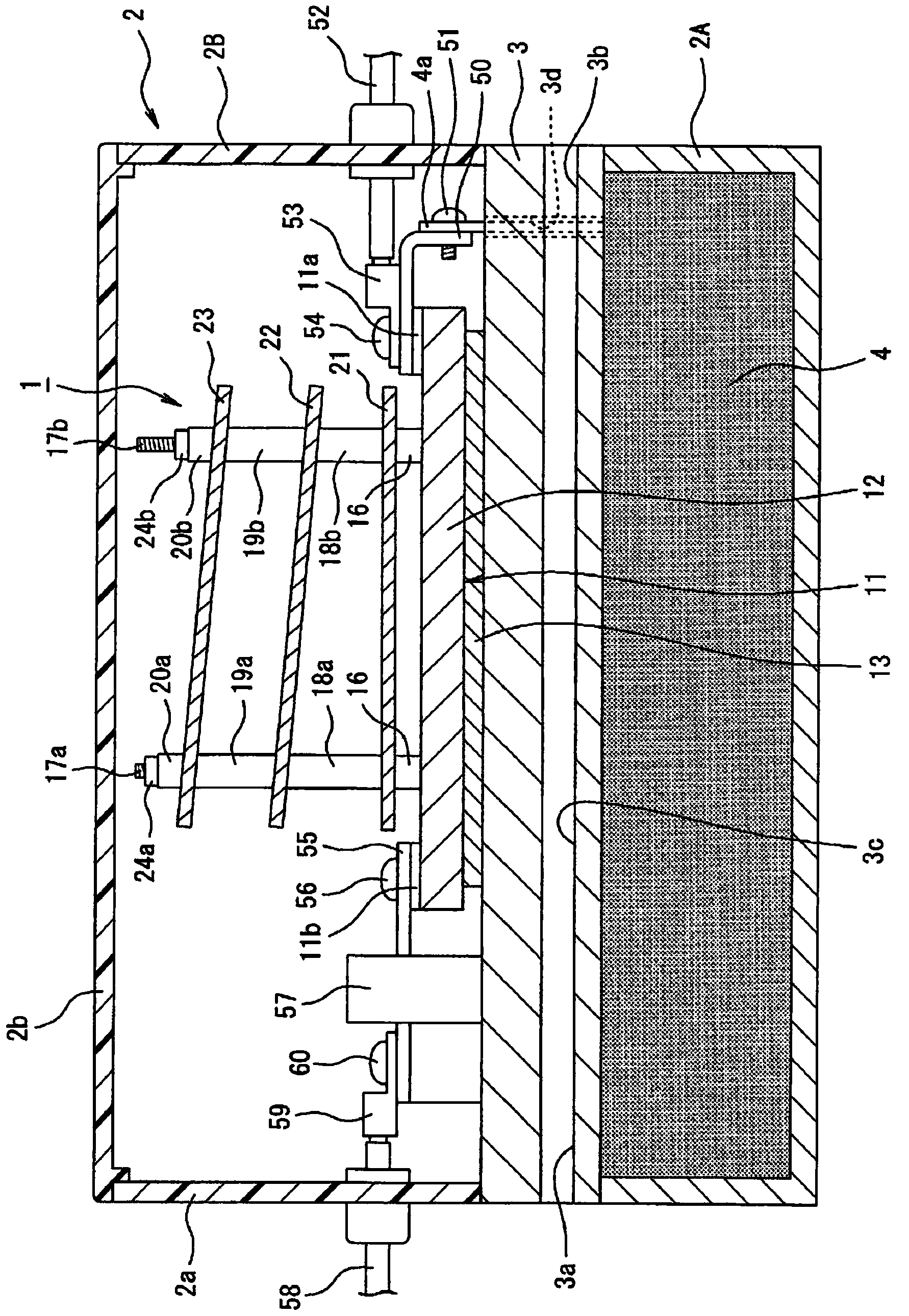
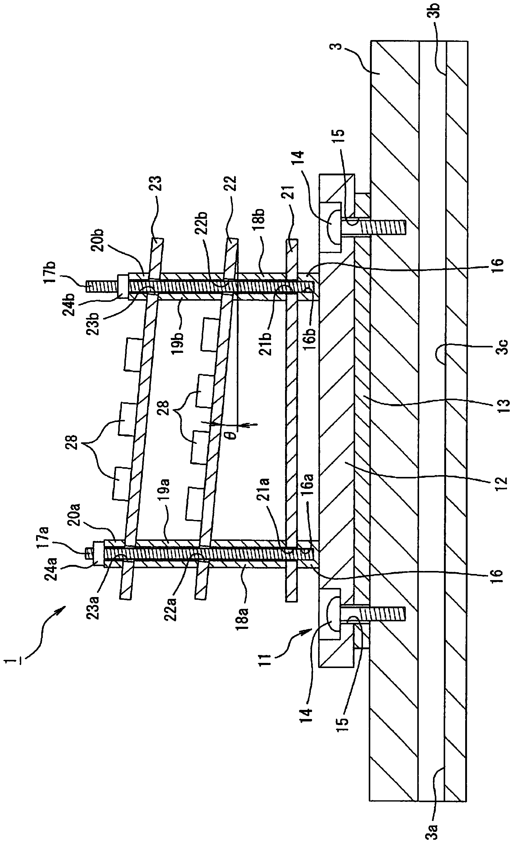
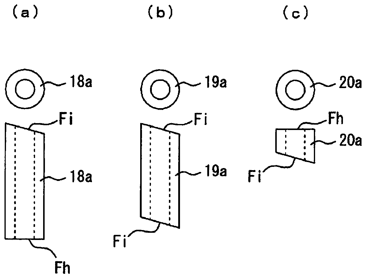
Provided is a power conversion device capable of preventing the occurrence of heat pockets by activating natural convection between mounted substrates. A power conversion device (1) is provided with a semiconductor power module (11) having one surface joined to a cooling body (3), and a plurality of mounted substrates (22, 23) laminated on the other surface of said semiconductor power module via an air layer and having mounted thereon circuit components including a heating circuit component (28) for driving said semiconductor power module. Said plurality of mounted substrates is tilted with respect to a flat surface orthogonal to the direction of gravity.

Description

technical field [0001] The present invention relates to a power conversion device. In the power conversion device, a semiconductor power module incorporating a semiconductor switching element for power conversion is supported with a predetermined interval on a semiconductor power module. Circuit components of heating circuit components of semiconductor switching elements. Background technique [0002] As such a power conversion device, the power conversion device described in Patent Document 1 is known. In this power conversion device, a water-cooling jacket is arranged in the casing, and a semiconductor power module is arranged on the water-cooling jacket to cool the semiconductor power module. The semiconductor power module has a built-in semiconductor switching element as a power conversion the IGBT. In addition, in the casing, a control circuit board is arranged at a predetermined distance on the opposite side of the semiconductor power module to the water-cooling jack...

Claims


Application Information

Patent Timeline
Patent Type & Authority Applications(China)
IPC IPC(8): H02M7/48H05K7/14H05K7/20
CPCH05K7/20127H05K7/20927H05K7/14322
Inventor 柴田美里田中泰仁
Owner FUJI ELECTRIC CO LTD
Learn More