
Horizontally-hung type cutting-punching point connection combined female die device

A technology of cutting pressure points and dies, applied in metal processing equipment, forming tools, manufacturing tools, etc., can solve the problems of high manufacturing cost, material fatigue, inconvenient maintenance, etc., and achieve high service life, high compressive strength, running stable effect

Active Publication Date: 2014-07-23
苏州托克斯冲压设备有限公司
View PDF9 Cites 0 Cited by
  • Summary
  • Abstract
  • Description
  • Claims
  • Application Information

AI Technical Summary

Problems solved by technology

[0004] 1. Its structure is relatively complicated, and the components require compact fit with high precision and high manufacturing cost;
[0005] 2. Since the opening and closing of the split flap is based on the positioning of the rotating shaft, the cutting edge is at a high position when the split flap is opened, and it frequently rubs against the plate, which accelerates the wear of the cutting edge and shortens the service life of the overall mold;
[0006] 3. Since the spring is built in the main body of the die, the split valves are installed with the die body through the pin shaft, which makes the assembly process complicated, the assembly operation is difficult, the maintenance is inconvenient, and it is labor-intensive and time-consuming
Frequent extrusion will cause fatigue to the material of the main body of the die, and a weak point will appear in the supporting part of the hollow structure in the middle, which will cause fatigue damage and cause the main body of the die to break and be scrapped

Method used


Image

  • Horizontally-hung type cutting-punching point connection combined female die device
  • Horizontally-hung type cutting-punching point connection combined female die device
  • Horizontally-hung type cutting-punching point connection combined female die device

Examples


Embodiment Construction

[0038] The preferred embodiments of the present invention will be described in detail below in conjunction with the accompanying drawings, so that the advantages and features of the present invention can be more easily understood by those skilled in the art, so as to define the protection scope of the present invention more clearly.

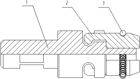
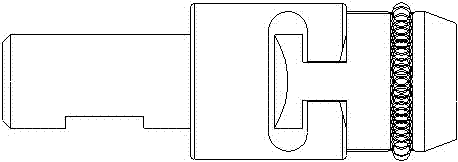
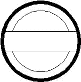
[0039] See attached figure 1 , 2As shown in , 3, each view reflects the structure of the combined die device connected by the horizontal cutting pressure point. Combined into a die device; this die device is matched with the corresponding punch to have the functions of cutting and separation, stretching deformation, extrusion and inlay at the connection point of the plate, and can complete the connection of a certain part of the plate at one time. In terms of structural design, the number of accessories should be reduced as much as possible, and the pressure center of the main body should not be equipped with a leaky slot structure, so as to ens...


PUM


Abstract

The invention discloses a horizontally-hung type cutting-punching point connection combined female die device which comprises a female die body, at least two sectioning blocks and an elastic ring. The female die body comprises a supporting base, a fixing column and a middle supporting plate, a transverse groove extending in the transverse direction and a guide groove extending in the longitudinal direction are formed in the outer diameter of the supporting base, the guide groove is perpendicular to the transverse groove, the guide groove and the transverse groove form a T-shaped groove integrally, and the bottom of the transverse groove is in the shape of a half circular arc; the lower portion of each sectioning block is provided with a guide column extending in the longitudinal direction and a transverse column extending in the transverse direction, each transverse column is vertical to the corresponding guide column, each transverse column and the corresponding guide column form a T-shaped convex column correspondingly installed in the T-shaped groove integrally, and each transverse column is provided with a semicircular side correspondingly matched with the bottom of the transverse groove and accordingly a movable joint can be formed; transverse annular grooves are formed in the peripheries of the sectioning blocks, and the elastic ring is arranged in the annular grooves. By the adoption of the technological means, the device is simple in structure, low in cost, convenient to use, practical, flexible in joint, stable in operation and visual in observation, and the service life of the device is obviously longer than that of a female die in the prior art.

Description

technical field [0001] The technology relates to a die for connection of cut pressure points of metal plate parts, in particular to a horizontal hanging type cut pressure point connection combined die device widely used in the stamping field. Background technique [0002] At present, in the field of stamping, the point stamping connection technology of sheet metal parts through corresponding punches and dies has been widely used, especially in the metal sheet rivetless connection technology, the cutting point connection technology is becoming more and more mature, and it is used for stamping point connection. The mold device plays a vital role. The punch is an inverted trapezoidal flat cutting edge and the corresponding longitudinal concave opening groove to form a bilateral shearing trend. The plate placed between the punch and the die is under the action of the stamping force. , the two sides of the square connection point are cut into a concave and separated shape, while ...

Claims


Application Information

Patent Timeline
Patent Type & Authority Applications(China)
IPC IPC(8): B21D37/10B21D39/03
Inventor 张荣魁
Owner 苏州托克斯冲压设备有限公司
Learn More