A High Precision Thick Foil Scissors Axis System

A technology of cutter shaft and system device, which is applied in the direction of cutter, shearing device, metal processing, etc. for shearing machine device, can solve the problems of low precision, large accumulated error, friction and heating, etc., to ensure the accuracy of radial clearance , the effect of reducing difficulty and easy maintenance

Active Publication Date: 2016-08-17
辽宁省机械研究院有限公司
View PDF5 Cites 0 Cited by
  • Summary
  • Abstract
  • Description
  • Claims
  • Application Information

AI Technical Summary

Problems solved by technology

[0003] 1. The rear end of the front part of the cutter shaft system is installed with cylindrical roller bearings. The clearance of the bearings cannot be precisely controlled, and once the installation is completed, the clearance cannot be adjusted. When the cutter shaft rotates at a high speed, the bearing may vibrate slightly or Friction heating and other issues
[0004] 2. Three angular contact ball bearings are installed on the front end of the front part of the cutter shaft system, and the adjacent two bearings of the three angular contact ball bearings are installed with inner and outer spacers, so that the clearance of this part of the bearings can be adjusted , but it greatly increases the difficulty of processing and assembly, and the cumulative error is large
[0005] 3. The cutter shaft is a welded part with low precision, and the tail is a tapered surface. The tapered surface needs to cooperate with the inner tapered sleeve, so the precision is high and the processing is difficult. Moreover, once the cutter shaft is worn, it is difficult to repair the tapered surface.

Method used


Image

  • A High Precision Thick Foil Scissors Axis System
  • A High Precision Thick Foil Scissors Axis System

Examples


Embodiment Construction

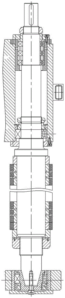
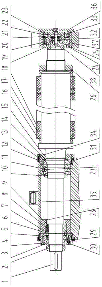
[0018] The cutter shaft system device realized by the present invention is as figure 1 As shown, it specifically includes cutter shaft 1, nut 1 2, bearing cap 3, spacer 1 4, angular contact ball bearing 5, spacer ring 1 6, spacer ring 2 7, angular contact ball bearing 2 8, angular contact ball bearing Three 9, nut two 10, spacer two 11, cylindrical roller bearing one 12, bearing housing one 13, spacer three 14, gland 15, reference ring 16, spacer ring 17, disc cutter 18, inner taper sleeve 19 , Cylindrical roller bearing two 20, spacer four 21, spacer five 22, nut three 23, spacer six 24, spacer seven 25, nut four 26, spacer eight 27, bearing seat two 28, screw one 29, Screw two 30, screw three 31, screw four 32, screw five 33, screw six 34, box body 35, end cover 36, bearing seat three 37, outer taper sleeve 38. Among them, the cutter shaft 1 is a forged integral type, and the rear end of the cutter shaft 1 is a cylindrical surface; the rear end support bearing of the front ...


PUM


Abstract

The invention discloses a high-precision thick foil scissor cutter shaft system. A cutter shaft is in a forging integrated type, a supporting bearing at the rear end of the front part of the cutter shaft system is a cylindrical roller bearing, wherein an inner ring of the cylindrical roller bearing is a conical face, the inner ring and an outer ring of the cylindrical roller bearing are separable, and the inner ring is completely fixed on the cutter shaft through a nut. Two spacer bushes are mounted between a first angular contact ball bearing and a second angular contact ball bearing at the front end of the front part of the cutter shaft system, the inner ring is locked on the cutter shaft through the nut. The supporting bearing at the rear end of the cutter shaft system is the cylindrical roller bearing with the inner ring being the conical face and the inner ring and the outer ring being separable, the inner ring of the bearing can be fixed on an inner conical sleeve through the nut, a separation ring is arranged on the inner ring of the bearing, and an outer conical sleeve is fixed on the cylindrical face of the rear end of the cutter through a screw. The high-precision thick foil scissor cutter shaft system can obviously improve the cutting precision, the heating problem of the bearings in the high speed operation process is solved, mounting and adjusting are convenient, and the production efficiency of shearing equipment is improved.

Description

technical field [0001] The invention relates to a cutter shaft system device used for a cutter holder of a metal strip longitudinal shearing device. Background technique [0002] Thick foil shears and disc shears are the main equipment for longitudinal shearing of steel and non-ferrous metal strips. Their main function is to cut the coiled strips into strips of specified width according to the corresponding functions. The cutter shaft system device is the core component of each shearing equipment, and its rotation accuracy directly determines the shearing accuracy of the shearing equipment. However, the traditional mechanical structure of the cutter shaft system is not reasonable enough. Disassembly is more complicated, which affects the efficiency of equipment operation. At present, the domestic conventional thick foil scissors shaft structure is as follows: figure 1 As shown, its main problems are: [0003] 1. The rear end of the front part of the cutter shaft system is...

Claims


Application Information

Patent Timeline
Patent Type & Authority Patents(China)
IPC IPC(8): B23D35/00B23P11/00
Inventor 张洪锐王建珩张庆生于鹏飞
Owner 辽宁省机械研究院有限公司
Why Eureka
Try Eureka