Automatic member-embedding injection mould

An insert injection molding and mold technology, applied in the direction of coating, etc., can solve the problems of limited connection accuracy, discontinuous production process, long production cycle, etc., and achieve the effect of fast blanking, high stability and accurate positioning

Active Publication Date: 2014-07-23
NINGBO BEILONG PRECISION MOLDING
View PDF1 Cites 14 Cited by
  • Summary
  • Abstract
  • Description
  • Claims
  • Application Information

AI Technical Summary

Problems solved by technology

[0003] The purpose of the present invention is to overcome the problem of limited connection accuracy, discontinuous production process and long production cycle of the optical fiber quick connector composed of ceramic ferrule inserts and flange core base plastic parts in the prior art during injection molding. Insufficient defects provide an automatic insert injection mold with automatic blanking, accurate positioning, high matching precision, continuous and efficient injection molding process

Method used


Image

  • Automatic member-embedding injection mould
  • Automatic member-embedding injection mould
  • Automatic member-embedding injection mould

Examples


Embodiment 1

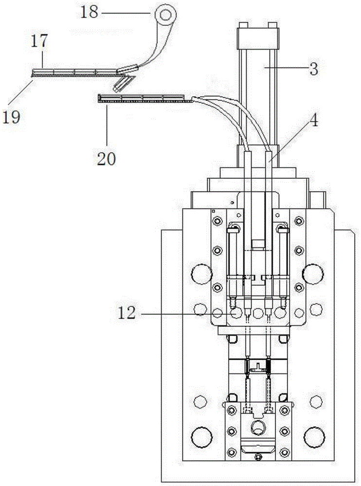
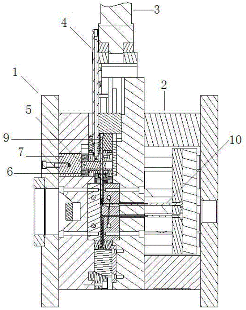
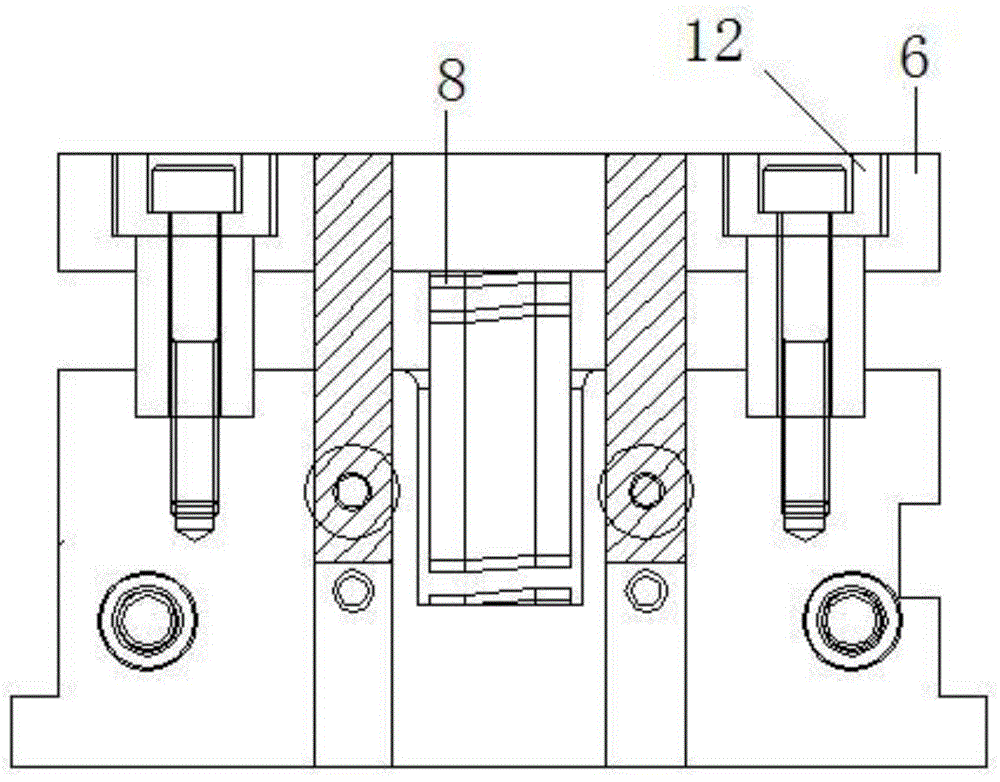
[0024] Such as figure 1 , figure 2 , image 3 , Figure 5 In the shown embodiment, an automatic insert injection mold includes an upper mold 1, a lower mold 2, a cylinder 3, and a blanking mechanism. The blanking mechanism includes a blanking tube 4 connected to a vibrating plate. The lower end of the feeding pipe 4 is provided with a feeding push block 5 with a material holding hole, and the feeding push block 5 is located in a push block groove slidingly connected with the feeding push block 5, and the described feeding push block 5 is provided with There is a push plate 6, the front of the push plate 6 is in contact with the upper mold pressing block 7 in the upper die 1, the back of the push plate 6 is provided with a spring 8, and the spring 8 is in a compressed state when the mold is closed. The blanking mechanism also includes a feeding push rod 9 driven by the cylinder 3. The lower end of the feeding push rod 9 is facing one end of the material holding hole, and th...

Embodiment 2

[0027] In this embodiment, the basic structure and implementation mode are the same as in Embodiment 1, and the differences are as Figure 4 , Figure 6 , Figure 7 Shown in: described feeding pipe 4 is provided with air intake pushing structure, and described air feeding pushing structure comprises main air pipe 14, and described main air pipe 14 is connected with some oblique air pipes 15, and oblique air pipe 15 is connected with unloading pipe 4 communicated, and the communication position between the inclined air pipe 15 and the feeding pipe 4 is at the lower part of the inclined air pipe 15 and above the pre-embedded position. The main air pipe 14 is used to connect air supply devices such as air pumps. During blanking, the air supply device supplies gas, and the gas is blown into and pressed into the lower part of the feeding pipe 4 through the inclined air pipe 15 to promote the ceramic ferrule 17. The assembly and connection precision of the ceramic ferrule 17 is re...


PUM


Abstract

The invention discloses an automatic member-embedding injection mould. The automatic member-embedding injection mould has the advantages of automatic blanking, accurate positioning, high cooperation precision, and continuous and high efficiency injection moulding process. The automatic member-embedding injection mould comprises an upper die, a lower die, a cylinder and a blanking mechanism; the blanking mechanism comprises a blanking tube, a feeding push block with an accommodation hole is arranged at the lower part of the blanking tube, the feeding push block is positioned in a block pushing groove connected to the feeding push block in a slide mode, a compression extrusion plate is arranged besides the feeding push block, the right side of the compression extrusion plate is contacted to an upper die briquetting in the upper die, a spring is provided at the back of the compression extrusion plate, the spring is in a compaction state while the mould is closed, the blanking mechanism also comprises a feeding push rod driven by the cylinder, the lower end of the feeding push rod just faces to one end of the accommodation hole, a pre-embedding position in the mould cavity is positioned at the lower part of the accommodation hole, and a discharging push rod is provided on the lower die. The automatic member-embedding injection mould has the advantages of automatic feeding and blanking, rapid blanking in place and accurate positioning, the stability is high while injection moulding, and the cooperation precision of the molded product is guaranteed.

Description

technical field [0001] The invention belongs to the technical field of mold forming, and in particular relates to an automatic insert injection mold. Background technique [0002] Optical fiber quick connector is one of the key components in the field of optical fiber to the home. It is mainly used for the connection and fixing of optical fiber, and it has high requirements for precision. Among the current optical fiber quick connectors, there is a more commonly used one, which is composed of ceramic ferrule inserts and plastic parts of flange core bases. The ceramic ferrule inserts are equipped with optical fiber holes, and some apertures are very small or require high precision. In some cases, one end of the ceramic ferrule will also have a chamfered groove to facilitate the entry of optical fibers. There are roughly two ways to form this kind of quick joint, one is to glue the ceramic ferrule and flange core plastic parts together for processing, and the other is to use ...

Claims


Application Information

Patent Timeline
Patent Type & Authority Applications(China)
IPC IPC(8): B29C45/26B29C45/32B29C45/14
CPCB29C45/14008B29C45/14073B29C45/32B29C2045/14163
Inventor 熊海锦
Owner NINGBO BEILONG PRECISION MOLDING
Why Eureka
Try Eureka