
Liquid ejection head manufacturing method, liquid ejection head and printing device

A technology of a liquid nozzle and a manufacturing method, applied in the field of printing, can solve the problems of high manufacturing cost, low yield of liquid nozzles, poor printing quality, etc., and achieve the effects of improving the yield, avoiding damage, and improving printing quality.

Active Publication Date: 2016-04-20
DALIAN UNIV OF TECH +1
View PDF6 Cites 0 Cited by
  • Summary
  • Abstract
  • Description
  • Claims
  • Application Information

AI Technical Summary

Problems solved by technology

[0005] The invention provides a liquid nozzle manufacturing method, a liquid nozzle and a printing device, which are used to solve the technical defects of the liquid nozzle manufactured by the liquid nozzle manufacturing method in the prior art, such as low yield, high manufacturing cost and poor printing quality

Method used


Image

  • Liquid ejection head manufacturing method, liquid ejection head and printing device
  • Liquid ejection head manufacturing method, liquid ejection head and printing device
  • Liquid ejection head manufacturing method, liquid ejection head and printing device

Examples


Embodiment Construction

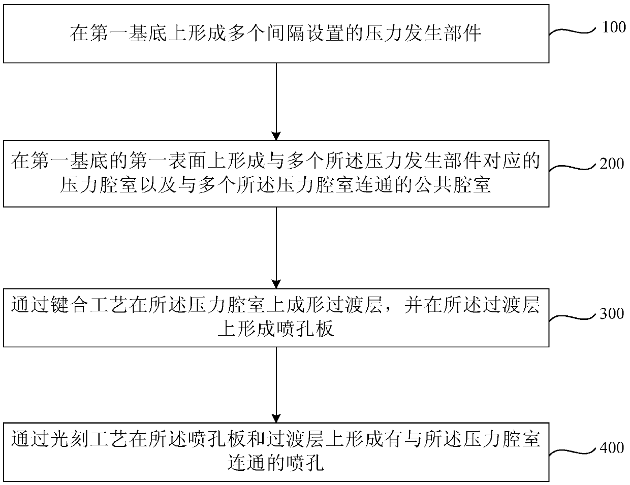
[0024] figure 1 A flow chart of a liquid nozzle manufacturing method provided by an embodiment of the present invention, such as figure 1 As shown, the liquid nozzle manufacturing method provided in this embodiment includes:

[0025] Step 100, forming a plurality of spaced apart pressure generating components on a first substrate.

[0026] Step 200, forming pressure chambers corresponding to the plurality of pressure generating components and a common chamber communicating with the plurality of pressure chambers on the first surface of the first substrate.

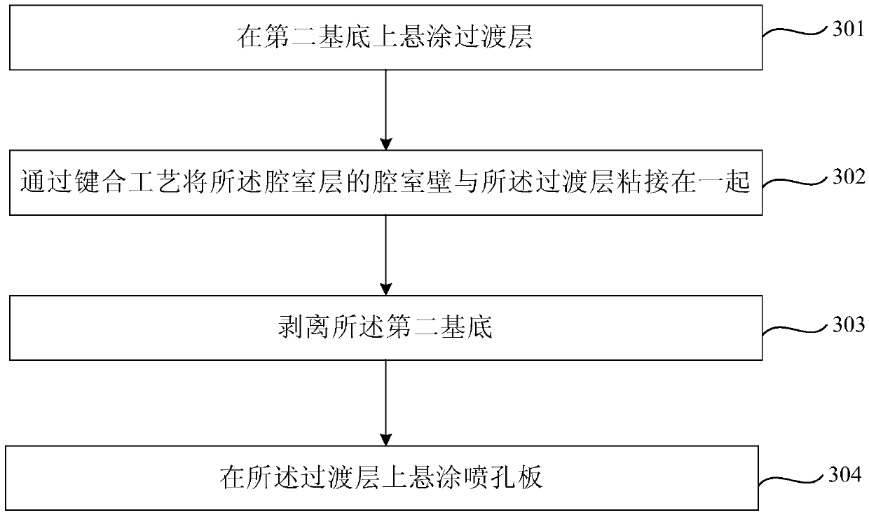
[0027] specifically, figure 2 for figure 1 A flowchart of a specific embodiment of step 200; as figure 2 As shown, step 200, forming pressure chambers corresponding to the plurality of pressure generating components on the first surface of the first substrate and a common chamber communicating with the plurality of pressure chambers may include:

[0028] Step 201, disposing and exposing a chamber layer on the first ...


PUM


Abstract

The invention provides a liquid jet manufacturing method, a liquid jet and a printing device. The liquid jet manufacturing method comprises forming a plurality pressure generating units at intervals on a first substrate; forming a plurality of pressure cavities, which correspond to the pressure generating units, and a plurality of common cavities communicated with the pressure cavities on the first surface of the substrate; forming transition layers on the pressure cavities through the bonding process, and forming a jet hole plate on the transition layers; forming jet holes communicated with the pressure cavities on the jet hole plate and the transition layers through the photoetching process. According to the liquid jet manufacturing method, the pressure cavities and the common cavity are formed on the first surface of the first substrate, so that when more pressure cavities of liquid jets are required, the pressure cavities can be formed independently on the first substrate without reducing the mechanical strength of the first substrate; during the manufacturing process, damage to the first substrate can be avoided, so that the yield rate of the liquid jets can be improved, and the manufacturing cost can be reduced.

Description

technical field [0001] The invention relates to printing technology, in particular to a method for manufacturing a liquid ejection head, a liquid ejection head and a printing device. Background technique [0002] The liquid nozzle of the printer changes the volume of the pressure chamber through the deformation of the piezoelectric element and the vibration plate, so that the ink in the pressure chamber is ejected from the nozzle hole. [0003] A conventional liquid spray head includes a substrate, a vibrating plate and a piezoelectric element arranged on the first surface of the substrate, and an orifice plate bonded on the second surface of the substrate (the surface opposite to the first surface). The existing manufacturing method of the liquid ejection head is: form a vibrating plate and a piezoelectric element on the first surface of the substrate, and etch a plurality of corresponding piezoelectric element positions on the substrate through an etching process on the se...

Claims


Application Information

Patent Timeline
Patent Type & Authority Patents(China)
IPC IPC(8): B41J2/16B41J2/14B41J2/01
Inventor 邹赫麟何敬志李越陈晓坤
Owner DALIAN UNIV OF TECH
Learn More