Winding machine spindle clamping device

A clamping device and winding machine technology, which is applied in the field of winding machines, can solve the problems of poor resilience of spring sheets, increase production costs, and reduce work efficiency, etc., and achieve the effects of enhancing elasticity, improving work efficiency, and long service life

Inactive Publication Date: 2014-07-23
李雪明
View PDF11 Cites 5 Cited by
  • Summary
  • Abstract
  • Description
  • Claims
  • Application Information

AI Technical Summary

Problems solved by technology

[0002] The winder is a common textile machine in the textile industry, and the spindle clamping device is an important part of the winder. Generally, two chucks are installed at the upper end and the lower end of the clamping device to fix the spindle. , in actual production, according to the different types of yarns, different yarn bobbins should be selected, but the diameter of the chuck is fixed, so every time the type of yarn bobbin is changed, the chuck must be changed accordingly, which is troublesome , which reduces the work efficiency, and a few parts use springs to replace the collets, and use the elastic recovery force of the springs to fix the yarn bobbin. This structure will be more convenient to use at the beginning, but as time goes by As time goes on, the resilience of the spring will become worse and worse, and it will not be able to achieve a good effect, so the spring needs to be replaced frequently, which increases the production cost

Method used


Image

  • Winding machine spindle clamping device

Examples


Embodiment Construction

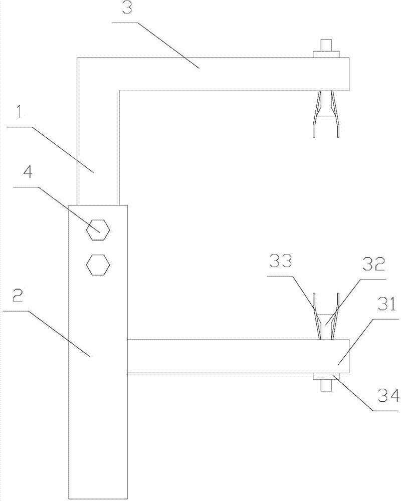
[0011] The present invention is described in further detail now in conjunction with accompanying drawing. These drawings are all simplified schematic diagrams, which only illustrate the basic structure of the present invention in a schematic manner, so they only show the configurations related to the present invention.

[0012] Such as figure 1 As shown, a winding machine spindle clamping device includes an upper support bar 1, a lower support bar 2 and two clamping assemblies 3, the upper support bar 1 and the lower support bar 2 are perpendicular to the horizontal plane, and the upper support bar 2 is perpendicular to the horizontal plane. The support rod 1 is arranged above the lower support rod 2, the upper support rod 1 is slidably connected with the lower support rod 2, and the two clamping assemblies 3 are fixedly connected with the upper support rod 1 and the lower support rod 2 respectively, and the two clamping assemblies 3 are connected to each other. Symmetrical, ...


PUM


Abstract

The invention relates to a winding machine spindle clamping device which comprises an upper supporting rod, a lower supporting rod and two clamping modules. Every clamping module comprises a beam, a spring piece, a bolt and a nut, wherein one end of the beam far away from the supporting rods is provided with a small hole, the diameter of the small hole is smaller than that of the head of the bolt, the bolt penetrates the small hole to be fixed on the beam through the nut, the spring piece is fixed on the beam, the spring piece and the head of the bolt are located on the same side of the beam, the top end of the spring piece abuts against a threaded rod of the bolt, and the middle of the spring piece abuts against the head of the bolt. The spring pieces of the two clamping modules are oppositely arranged between the two beams. By adjusting the height of the upper supporting rod, the distance between the two clamping modules is adjusted; by additionally arranging the bolts between the spring pieces, elasticity of the spring pieces is improved by utilizing the working principle of an expansion screw and external force, the service life of the whole device is longer, a spindle is clamped more stably, the device is simple to operate, the applied range of the device is increased, and working efficiency is improved.

Description

technical field [0001] The invention relates to a winding machine, in particular to a winding machine spindle clamping device. Background technique [0002] The winder is a common textile machine in the textile industry, and the spindle clamping device is an important part of the winder. Generally, two chucks are installed at the upper end and the lower end of the clamping device to fix the spindle. , in actual production, according to the different types of yarns, different yarn bobbins should be selected, but the diameter of the chuck is fixed, so every time the type of yarn bobbin is changed, the chuck must be changed accordingly, which is troublesome , which reduces the work efficiency, and a few parts use springs to replace the collets, and use the elastic recovery force of the springs to fix the yarn bobbin. This structure will be more convenient to use at the beginning, but as time goes by As time goes on, the resilience of the spring sheet becomes worse and worse, a...

Claims


Application Information

Patent Timeline
Patent Type & Authority Applications(China)
IPC IPC(8): B65H54/553
Inventor 李雪明
Owner 李雪明
Why Eureka
Try Eureka