Hydraulic multiple frequency ultrasonic sounder

A sounder and ultrasonic technology, applied in the direction of sounding equipment, instruments, etc., can solve the problems of difficult sound pressure amplitude, difficult application of reed whistle engineering, and difficulty in further improving cavitation intensity

Inactive Publication Date: 2015-11-18
SHAANXI NORMAL UNIV
View PDF3 Cites 0 Cited by
  • Summary
  • Abstract
  • Description
  • Claims
  • Application Information

AI Technical Summary

Problems solved by technology

However, the inventor found in further research that the traditional reed whistle still has a single frequency in sewage treatment, and it is difficult to greatly increase the sound pressure amplitude, which makes it difficult to further improve the cavitation intensity. brings difficulties

Method used


Image

  • Hydraulic multiple frequency ultrasonic sounder

Examples


Embodiment 1

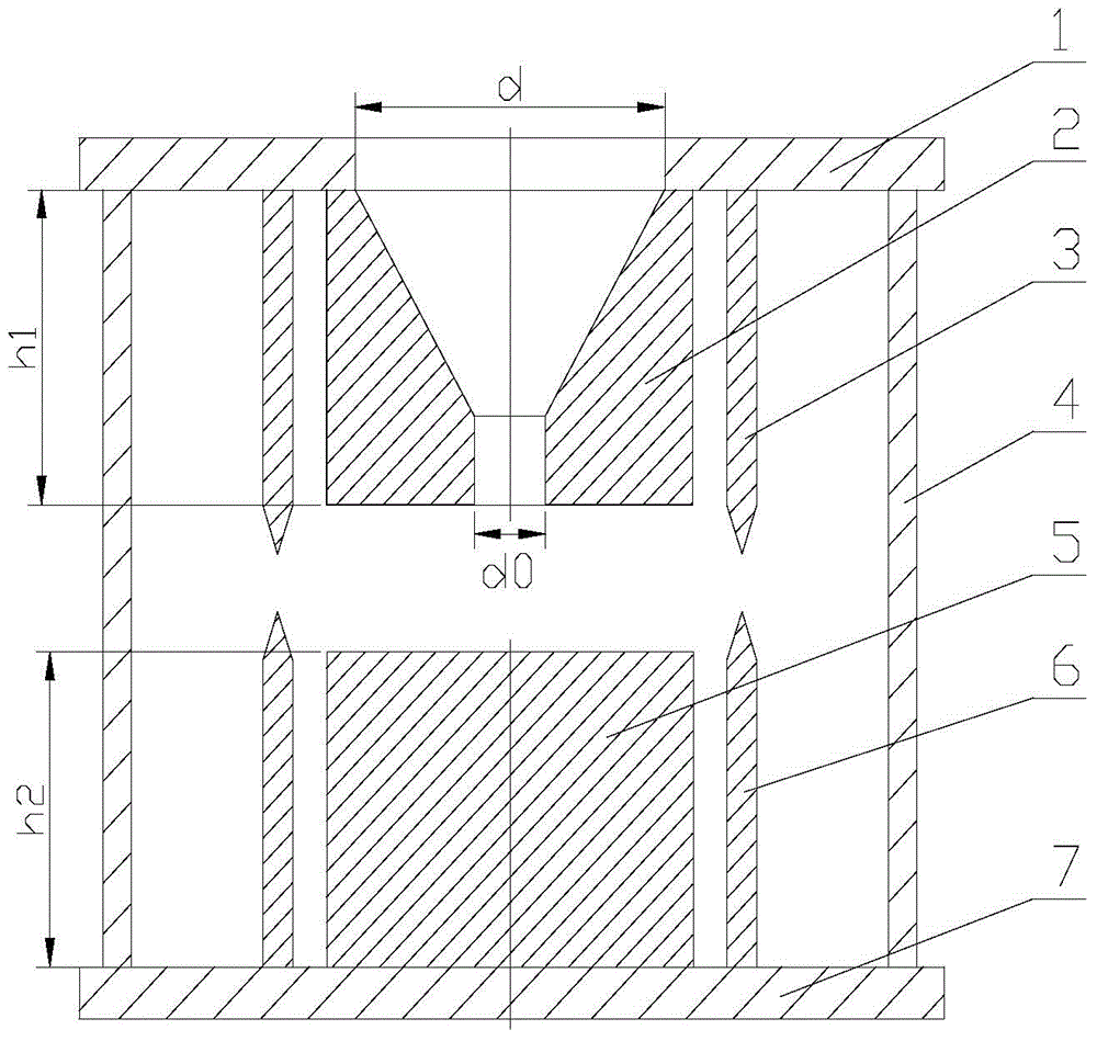
[0013] Depend on figure 1 It can be seen that the hydraulic multi-frequency ultrasonic sounder of this embodiment is composed of the inlet plate 1 , the nozzle 2 , the inlet reed 3 , the connecting rod 4 , the barrier body 5 , the bottom reed 6 and the chassis 7 .

[0014] The inlet plate 1 and the chassis 7 of the present embodiment are circular plates made of stainless steel, and the inlet plate 1 and the chassis 7 are connected by four connecting rods 4 evenly distributed on the same circumference. A fluid inlet is processed in the center of the fluid inlet, and a converging nozzle 2 extending inward is installed on the fluid inlet. The inlet diameter d of the nozzle 2 is 8mm, and the outlet diameter d 0 is 4mm, and the length h1 is 30mm, that is, the inlet diameter d and the outlet diameter d 0 The ratio is 1:0.5, 6 inlet reeds 3 are installed on the outside of the nozzle 2 at a position 2mm away from the outer wall of the nozzle 2, and the 6 inlet reeds 3 are symmetrical...

Embodiment 2

[0017] In this embodiment, the inlet plate 1 and the chassis 7 are connected by two connecting rods 4 evenly distributed on the same circumference. A fluid inlet is processed in the center of the inlet plate 1, and a fluid inlet extending inward is installed on the fluid inlet. Convergent nozzle 2, the inlet diameter d of nozzle 2 is 8mm, and the outlet diameter d 0 is 3.2mm, and the length h1 is 30mm, that is, the inlet diameter d and the outlet diameter d 0 The ratio is 1:0.4. Eight inlet reeds 3 are installed on the outside of the nozzle 2 at a position 3mm away from the outer wall of the nozzle 2. The eight inlet reeds 3 are symmetrically distributed on the same circumference with respect to the center line of the nozzle 2. Each The entrance reed 3 has a length of 31mm and a thickness of 3mm, and its end is pointed, and the size of the pointed angle is 10°, and the generated ultrasonic frequency is 2.554kHz. A barrier body 5 is installed at the position facing the outlet ...

Embodiment 3

[0020] In this embodiment, the inlet plate 1 and the chassis 7 are connected by 8 connecting rods 4 evenly distributed on the same circumference. A fluid inlet is processed in the center of the inlet plate 1, and a fluid inlet extending inward is installed on the fluid inlet. Convergent nozzle 2, the inlet diameter d of nozzle 2 is 8mm, and the outlet diameter d 0 is 5.6mm, and the length h1 is 10mm, that is, the inlet diameter d and the outlet diameter d 0 The ratio is 1:0.7. Two inlet reeds 3 are installed on the outside of the nozzle 2 at a position 2mm away from the outer wall of the nozzle 2. The two inlet reeds 3 are symmetrically distributed on the same circumference with respect to the center line of the nozzle 2. Each The entrance reed 3 has a length of 11 mm and a thickness of 2 mm. Its end is pointed, and the size of the pointed angle is 15°. The generated ultrasonic frequency is 13.522 kHz. A barrier body 5 is installed at the position facing the outlet end of the...


PUM


Abstract

The invention relates to a hydraulic multi-frequency ultrasonic generator. At least two connecting rods are arranged between an inlet plate and a base plate; a convergent nozzle extending inwards is processed at the center of the inlet plate; at least two inlet spring plates are arranged on the outer side of the nozzle; a barrier body is arranged at the center of the base plate; the length of the barrier body is not equal to that of the nozzle; a bottom spring plate is arranged at the outer side of the barrier body. A liquid medium disturbs and generates retroaction on jet flow near the nozzle by using the jet flow from the nozzle and a barrier with a certain geometrical shape; alternating pressure field and speed field are generated between the nozzle and the barrier body; vibration is generated to generate a sound wave, so as to improve and intensify the ultrasonic wastewater treatment effect. The nozzle and the barrier are different in length, and the corresponding inlet spring plate and the bottom spring plate are also different in length, so that the multi-frequency ultrasonic wave is generated, the ultrasonic frequency can also be changed by changing the lengths of the nozzle, the barrier body, the inlet spring plate and the bottom spring plate, and the adjustable frequency is achieved.

Description

technical field [0001] The invention relates to a fluid sounder device for using fluid ultrasonic waves to degrade organic pollutants in an organic pollutant wastewater treatment system, in particular to a hydraulic multiple-frequency ultrasonic sounder. Background technique [0002] In the past two decades, my country's water pollution has been very serious. The main sources of water pollution are industrial wastewater, agricultural wastewater and urban domestic sewage. Especially the "three causes" (carcinogenic, teratogenic, and mutagenic) organic pollutants that are difficult to degrade, they not only consume a large amount of dissolved oxygen in the water body, make the water body lose the ability of self-purification, but also can exist in the environment for a long time, And through the food chain into the human body and gradually accumulated, has constituted a serious threat to human health. At the same time, due to the pollution of water bodies, many water resource...

Claims


Application Information

Patent Timeline
Patent Type & Authority Patents(China)
IPC IPC(8): G10K9/08
Inventor 沈壮志
Owner SHAANXI NORMAL UNIV
Why Eureka
Try Eureka