Turbulence resonance fluid sounder
A sounder and fluid technology, which is applied in the field of turbulent resonance fluid sounder, can solve problems such as difficulty in further improving cavitation intensity, difficulty in application of reed whistle engineering, and difficulty in finding nodes for reeds, so as to improve wastewater treatment effect and strengthen wastewater treatment. Treatment effect, low cost effect
- Summary
- Abstract
- Description
- Claims
- Application Information
AI Technical Summary
Problems solved by technology
Method used
Image
Examples
Embodiment 1
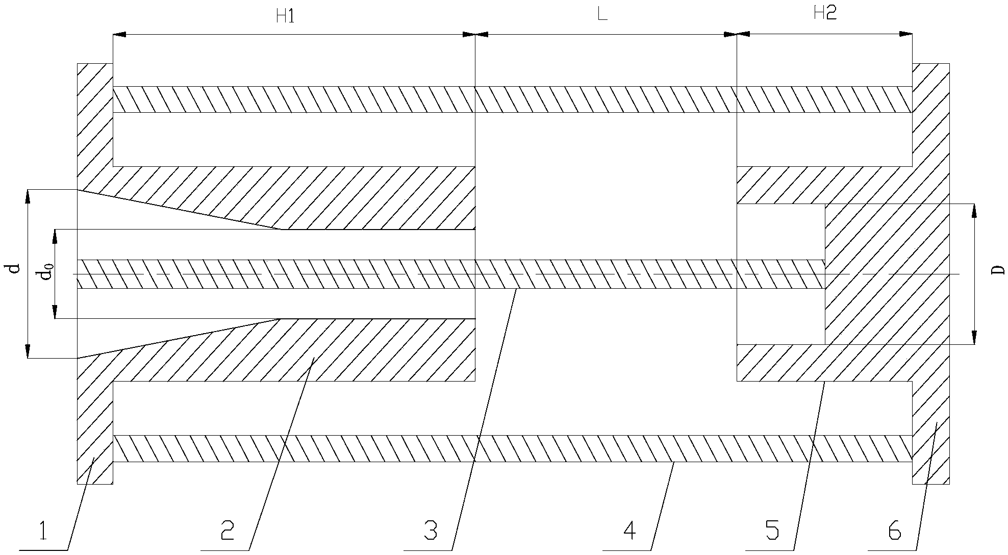
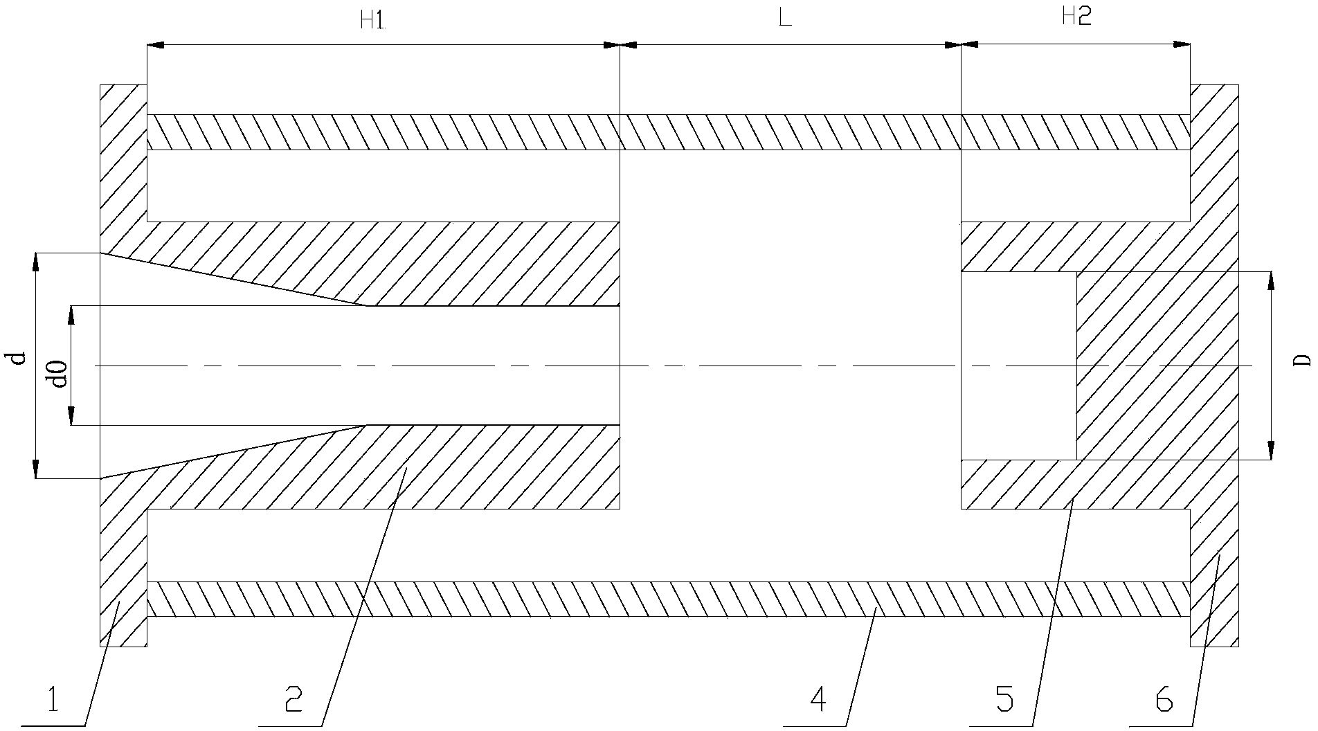
[0014] Depend on figure 1 It can be seen that the turbulent resonance fluid sound generator of this embodiment is composed of the inlet plate 1 , the nozzle 2 , the center rod 3 , the resonance rod 4 , the barrier body 5 and the chassis 6 .
[0015] The inlet disk 1 of the present embodiment is a circular plate made of stainless steel, and an inlet with a diameter of 20 mm is processed in the middle of the inlet disk 1, and the inlet extends inwardly to form a nozzle 2 that converges from large to small, and the nozzle 2 Depth H 1 is 48mm, and the outlet diameter is 10mm, that is, the inlet diameter d and outlet diameter d of nozzle 2 0 The ratio is 1:0.5. A circular stainless steel chassis 6 is installed under the inlet plate 1. A barrier body 5 is arranged coaxially with the nozzle 2 in the middle of the chassis 6. The barrier body 5 is a cavity with grooves processed on the top. structure, the periphery of the barrier body 5 is equal to the periphery of the nozzle 2, and ...
Embodiment 2
[0018] The inlet plate 1 of the present embodiment is a circular plate made of stainless steel, and the middle part of the inlet plate 1 is processed with an inlet with a diameter of 20 mm. The inlet extends inwardly to form a convergent nozzle 2. The depth H of the nozzle 2 is 1 is 48mm, and the outlet diameter is 6mm, that is, the inlet diameter d and outlet diameter d of nozzle 2 0 The ratio is 1:0.3. A circular stainless steel chassis 6 is installed under the inlet plate 1. A barrier body 5 is arranged coaxially with the nozzle 2 in the middle of the chassis 6. The barrier body 5 is a cavity with grooves processed on the top. Structure, the periphery of the barrier body 5 is equal to the periphery of the nozzle 2, the opening diameter D of the groove is equal to the outlet diameter d of the nozzle 2 0 Equal, ie 6mm, depth H 2 is 1mm, the wall thickness is 2.5mm, and the distance L between the top of the barrier body 5 and the outlet of the nozzle 2 is 1.2mm, which is 0.2 ...
Embodiment 3
[0021] The inlet plate 1 of the present embodiment is a circular plate made of stainless steel, and the middle part of the inlet plate 1 is processed with an inlet with a diameter of 20 mm. The inlet extends inwardly to form a convergent nozzle 2. The depth H of the nozzle 2 is 1 is 48mm, and the outlet diameter is 12mm, that is, the inlet diameter d and outlet diameter d of nozzle 2 0 The ratio is 1:0.6. A circular stainless steel chassis 6 is installed under the inlet plate 1. A barrier body 5 is arranged coaxially with the nozzle 2 in the middle of the chassis 6. The barrier body 5 is a cavity with grooves processed on the top. structure, the periphery of the barrier body 5 is equal to the periphery of the nozzle 2, and the opening diameter D of the groove is the outlet diameter d of the nozzle 2 0 1.17 times of , namely 14.04mm, depth H 2 The distance L between the top of the barrier body 5 and the outlet of the nozzle 2 is 8.424mm, which is 0.6 times of the diameter D of...
PUM
| Property | Measurement | Unit |
|---|---|---|
| diameter | aaaaa | aaaaa |
| depth | aaaaa | aaaaa |
| thickness | aaaaa | aaaaa |
Abstract
Description
Claims
Application Information
 - R&D
- Intellectual Property
- Life Sciences
- Materials
- Tech Scout
- Unparalleled Data Quality
- Higher Quality Content
- 60% Fewer Hallucinations
Browse by: Latest US Patents, China's latest patents, Technical Efficacy Thesaurus, Application Domain, Technology Topic, Popular Technical Reports.
© 2025 PatSnap. All rights reserved.Legal|Privacy policy|Modern Slavery Act Transparency Statement|Sitemap|About US| Contact US: help@patsnap.com


