Processing method of glass eyeglass of camera

A glass lens and processing method technology, applied in glass production, glass manufacturing equipment, glass cutting devices, etc., can solve the problems of reduced glass lens processing efficiency, low glass processing efficiency, uneven glass chamfering, etc., and achieves a high degree of automation. , to avoid uneven problems, to simplify the effect of processing

Active Publication Date: 2014-07-23
深圳市浩科投资咨询有限公司
View PDF5 Cites 10 Cited by
  • Summary
  • Abstract
  • Description
  • Claims
  • Application Information

AI Technical Summary

Problems solved by technology

[0002] In the process of processing the glass lens of the camera, the profiling machine is usually used to fix the pattern, and the sheets are stacked or singled out according to the thickness of the glass. Low, and manual chamfering can easily lead to uneven chamfering of the processed glass, poor dimensional accuracy, and even lead to the scrapping of the processed glass, which further reduces the processing efficiency of the glass lens

Method used


Image

  • Processing method of glass eyeglass of camera
  • Processing method of glass eyeglass of camera
  • Processing method of glass eyeglass of camera

Examples


Embodiment 1

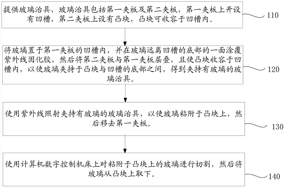
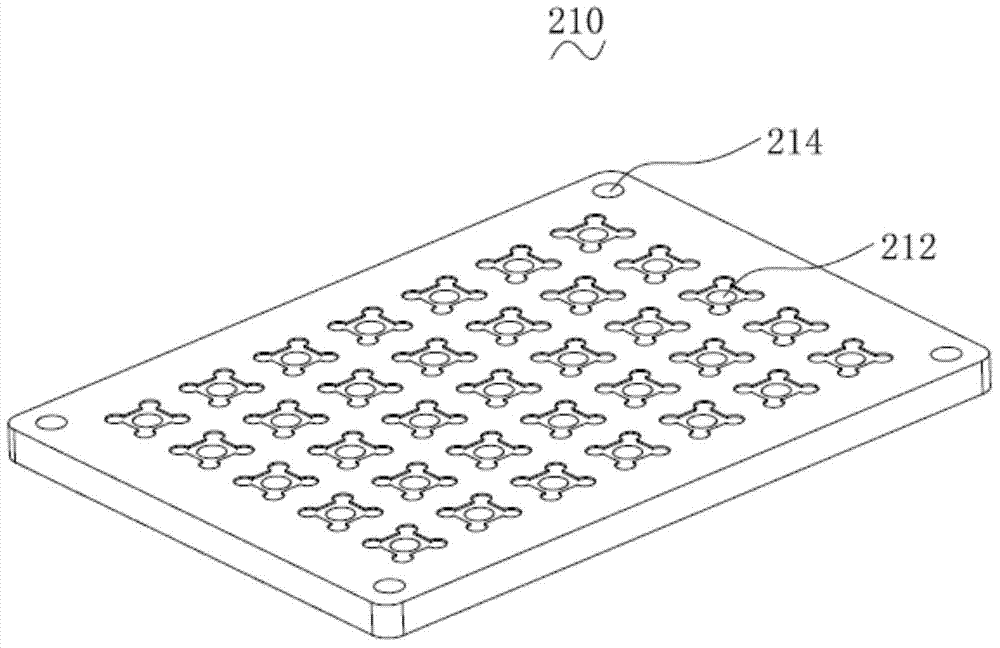
[0046] (1) Cut a large piece of raw glass into small pieces according to the product size, move the cut glass to the inserting workbench, the operator breaks the cut glass, and puts it flat into the empty tray; and then one by one Put the glass into the groove of the first splint, place a glass in each groove, fill the groove of the first splint with the glass, and visually check that there is no displacement when facing the light source.

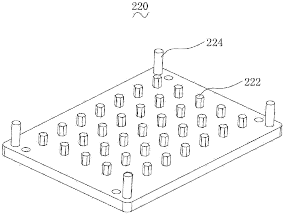
[0047] (2) Use a glue dispenser to apply UV-curable glue on the side of the glass away from the bottom of the groove, then place the second splint on the first splint, and accommodate the bumps in the groove so that the glass is clamped on the Between the end surface of the free end of the projection and the bottom of the groove, a glass fixture holding the glass is obtained.

[0048] (3) Then turn over the glass jig holding the glass so that the second splint is on top of the first splint. After standing for 5 minutes, use ultraviolet ligh...

Embodiment 2

[0052] (1) Cut a large piece of raw glass into small pieces according to the product size, move the cut glass to the inserting workbench, the operator breaks the cut glass, and puts it flat into the empty tray; and then one by one Put the glass into the groove of the first splint, place a glass in each groove, fill the groove of the first splint with the glass, and visually check that there is no displacement when facing the light source.

[0053] (2) Use a glue dispenser to apply UV-curable glue on the side of the glass away from the bottom of the groove, then place the second splint on the first splint, and accommodate the bumps in the groove so that the glass is clamped on the Between the end surface of the free end of the projection and the bottom of the groove, a glass fixture holding the glass is obtained.

[0054] (3) Then turn over the glass fixture holding the glass so that the second splint is on top of the first splint. After standing for 10 minutes, use ultraviolet...

Embodiment 3

[0058] (1) Cut a large piece of raw glass into small pieces according to the product size, move the cut glass to the inserting workbench, the operator breaks the cut glass, and puts it flat into the empty tray; and then one by one Put the glass into the groove of the first splint, place a glass in each groove, fill the groove of the first splint with the glass, and visually check that there is no displacement when facing the light source.

[0059] (2) Use a glue dispenser to apply UV-curable glue on the side of the glass away from the bottom of the groove, then place the second splint on the first splint, and accommodate the bumps in the groove so that the glass is clamped on the Between the end surface of the free end of the projection and the bottom of the groove, a glass fixture holding the glass is obtained.

[0060] (3) Then turn over the glass jig holding the glass so that the second splint is on top of the first splint. After standing for 8 minutes, use ultraviolet rays...


PUM

PropertyMeasurementUnit
wavelengthaaaaaaaaaa

Abstract

A processing method of a glass eyeglass of a camera comprises the following steps: providing a glass jig comprising a first clamping plate and a second clamping plate, wherein the first clamping plate is provided with a groove, the second clamping plate is provided with a projection, and the projection can be accommodated in the groove; putting glass in the groove of the first clamping plate, coating one surface of the bottom of the glass far from the groove with an ultraviolet-curable adhesive, laminating the first clamping plate and the first clamping plate, and allowing the projection to be accommodated in the groove to make glass clamped between the projection and the bottom of the groove in order to obtain a glass clamped glass jig; irradiating the glass clamped glass jig with ultraviolet ray to make the glass adhered to the projection, and removing the first clamping plate; and cutting the glass adhered on the projection by using a computer numerical control machine tool, and taking the glass off the projection. The processing efficiency of the processing method of the glass eyeglass of the camera is high.

Description

technical field [0001] The invention belongs to the field of processing glass lenses of cameras, in particular to a method for processing glass lenses of cameras. Background technique [0002] In the process of processing the glass lens of the camera, the profiling machine is usually used to fix the pattern, and the sheets are stacked or singled out according to the thickness of the glass. Low, and manual chamfering can easily lead to uneven chamfering of the processed glass, poor dimensional accuracy, and even lead to the scrapping of the processed glass, which further reduces the processing efficiency of the glass lens. Contents of the invention [0003] In view of this, it is necessary to provide a method for processing glass lenses of cameras with higher processing efficiency. [0004] A method for processing a glass lens of a camera, comprising the steps of: [0005] A glass fixture is provided, the glass fixture includes a first splint and a second splint, a groove...

Claims


Application Information

Patent Timeline
Patent Type & Authority Applications(China)
IPC IPC(8): C03B33/04
CPCY02P40/57
Inventor 刘浩然
Owner 深圳市浩科投资咨询有限公司
Why Eureka
Try Eureka